Down hole electrical connector and method for combating rapid decompression

a technology of electrical connectors and down holes, which is applied in the direction of connection contact materials, borehole/well accessories, coupling device connections, etc., can solve the problems of electrical faults in the connector itself, explosions or fires in hazardous areas, and substantial difficulties encountered heretofor

Active Publication Date: 2012-10-30
QUICK CONNECTORS
View PDF45 Cites 25 Cited by
  • Summary
  • Abstract
  • Description
  • Claims
  • Application Information

AI Technical Summary

Benefits of technology

[0011]To overcome the above and other problems, the preferred embodiment of the present invention includes a down hole connector that effectively seals the connector and internal elements of the electrical cable to prevent fluid discharge into hazardous areas. The preferred connector is sufficient to maintain a sealed mechanical and electrical connection between any two power cables, despite shifting and / or movement by the joined cables and well pressure events (pressurization and depressurization). The preferred connector is formed with a fluid sealing encasing material that surrounds and / or adheres to at least a portion of a the protective tubing surrounding an electrical cable's conductor wires. The encasing material may also surround and adhere to the conductive wire's insulation to prevent the insulation from changing physical dimensions during pressure events. A protective outer sleeve is positioned over the electrical cable so that it can engage the cable and be adhered to by the encasing material.

Problems solved by technology

Substantial difficulty has heretofore been encountered in providing a down hole connector assembly that prevents well fluids from permeating the connector and electrical cable assembly.
Fluid entering the connector can cause electrical faults in the connector itself, and can also escape through permeable portions of the electrical cable assembly into low pressure hazardous areas such as electrical enclosures within the well, above ground areas near the wellhead barrier, and even to the power transformer.
Explosions or fires may occur in hazardous areas due to gases and other substances associated with the production of petroleum products being ignited by electric arcs.
This endangers personnel and the general public by creating risk of electrical shock or death by electrocution in or near the hazardous area.
So far as known to applicant, the current art has failed to overcome the above and other problems.
It is substantially difficult, if not impossible, to initiate and / or maintain an effective seal where the corrugated cable passes through the wellhead barrier to prevent fluid discharge from the well.
It is also substantially difficult to seal the internal elements of a down hole connector and electrical cable from being permeated by well fluids.
The above mentioned problems worsen when pressure changes occur in the well.
Once the insulation is permeated, the fluid can flow through the electrical cable and out into hazardous areas creating a potentially explosive situation.
However, even if the two parts of the shield are fastened or otherwise locked together, as is typical, the pressure differentials in the well often cause a piston effect between the rubber boots that forces the electrical connection apart.
It has been discovered, however, that in certain applications well fluids may penetrate the insulator stand off surrounding the connector socket and reach the conductive wire.
However, so far as known to applicant, the attachment plug and receptacle connectors do not have such a rating and are incapable of withstanding an internal explosion without risk to the operator and drilling operations.
Another problem with the attachment plug and receptacle is that it frequently fails to stay connected when the well is suddenly pressurized or depressurized.
During pressurization the connector's internal rubber boots often become impregnated with fluid and expand, which may force apart the connector's mating counterparts.
During depressurization, fluid impregnated rubber boots may fail to release the fluids fast enough resulting a disconnect.

Method used


Image

  • Down hole electrical connector and method for combating rapid decompression
  • Down hole electrical connector and method for combating rapid decompression
  • Down hole electrical connector and method for combating rapid decompression

Examples


Embodiment Construction

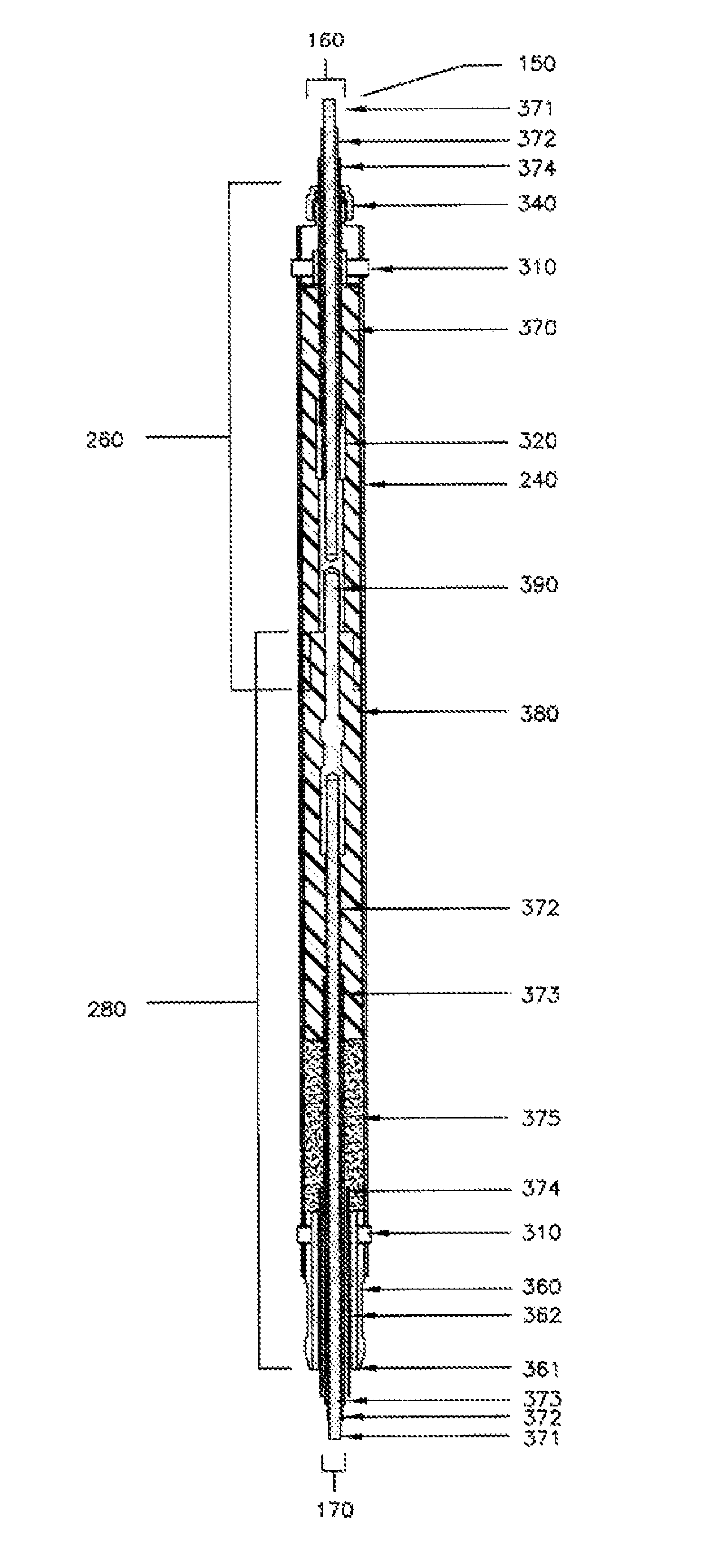
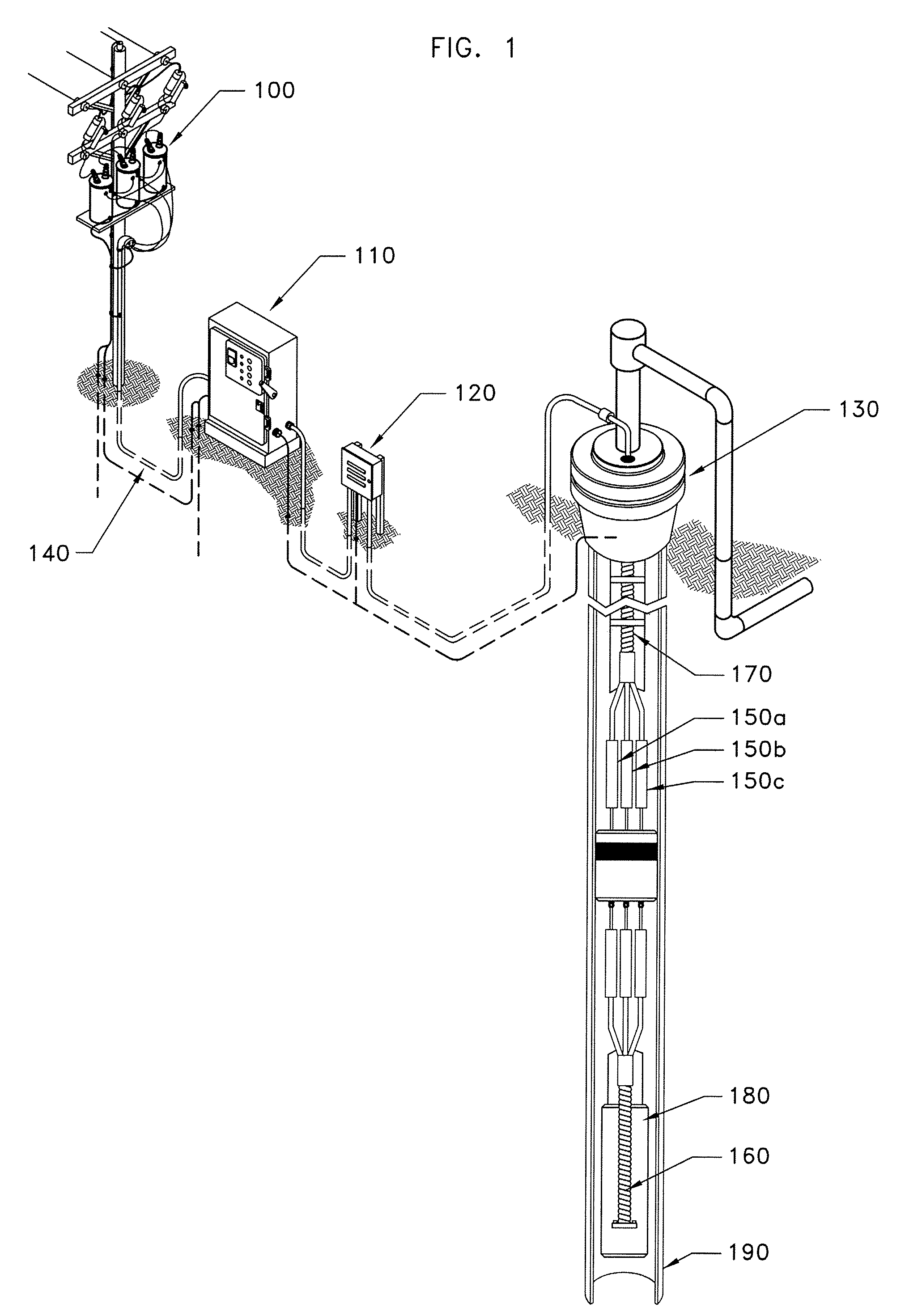
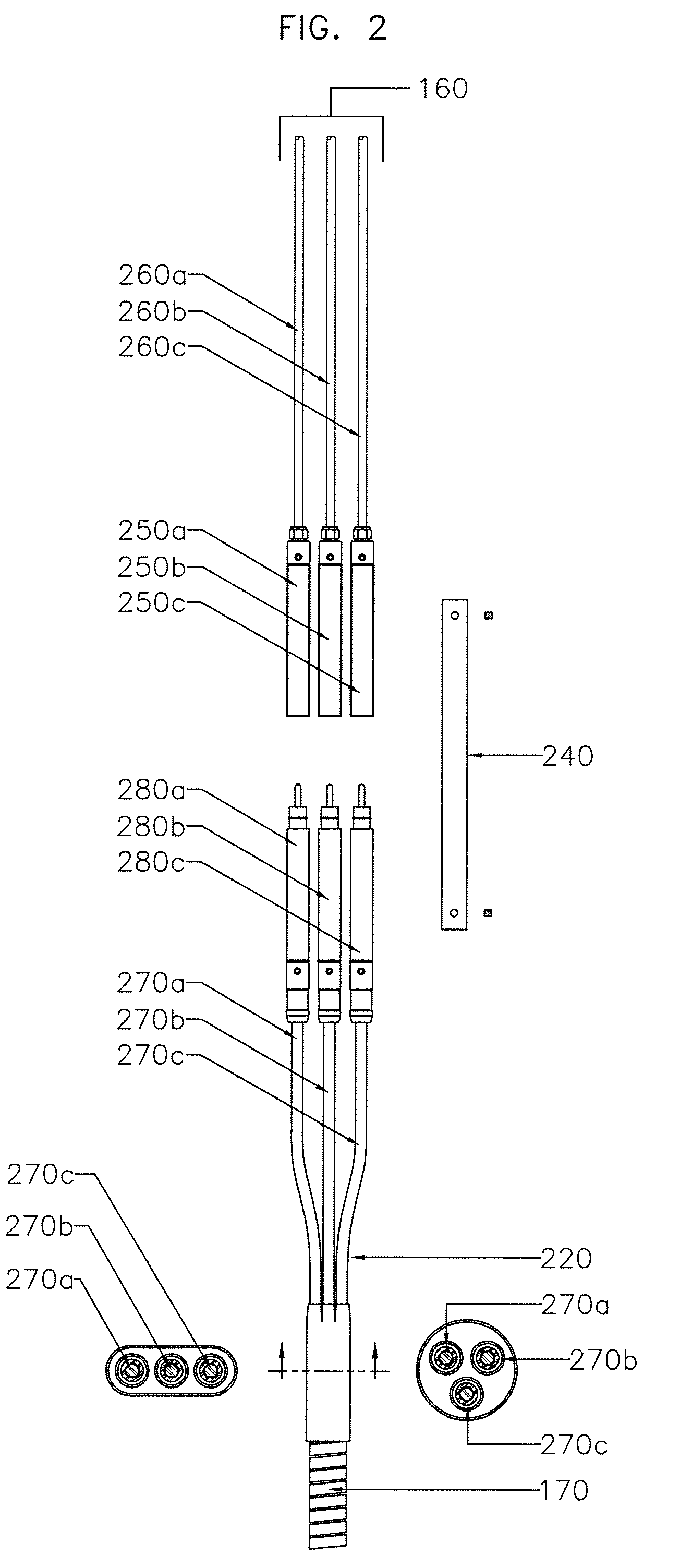
[0026]FIG. 1 illustrates a preferred embodiment of the invention in which a remote surface power source 100 provides electrical power to down hole electrical equipment. The remote power source 100 is preferably a transformer bank, positioned on a power pole, which supplies power via cable 140 to motor control panel 110. Electrical cable 140 is typically formed of a medium voltage electrical conductor cable that runs from the motor control panel 110 in a known way to a vented junction box 120, and then into a wellhead barrier 130 of an underground well. Inside the well, cable 170 extends from the wellhead barrier 130 below to a position down hole where an electrical connection will be made with a cable using preferred and alternative embodiments of the present invention. The connectors 150a, 150b, and 150c that are shown in FIG. 1 are each individually shown in FIGS. 1-8 as connector 150. The connectors provide the means for electrically and mechanically connecting cable 170 and cabl...


PUM


Abstract

Embodiments of the present invention provide an effective seal and connector that maintain a removable mechanical and electrical connection between any two down hole power cables, despite cable movement and well pressure. The connector preferably includes a fluid seal comprised an encasing material that surrounds and / or adheres to protective tubing encapsulating an electrical cable's conductor wires. The encasing material may also surround and / or adhere to the conductive wire's insulation to prevent its outward expansion during well pressure events. The connector's fluid seal also comprises a relatively rigid connection between the connector's protective outer sleeve and the protective tubing encapsulating the conductor wire.

Description

CROSS-REFERENCE TO RELATED APPLICATIONS[0001]This application claims the benefit of U.S. Provisional Application Ser. No. 60 / 888,250, filed Feb. 5, 2007, and U.S. Provisional Application Ser. No. 60 / 894,841, filed Mar. 14, 2007, and the contents of such applications are hereby incorporated by reference in their entirety.TECHNICAL FIELD[0002]The present invention relates to an electrical cable connector apparatus and method for an underground well. More particularly, the present invention relates to a simplified, low cost down hole electrical connector, and method for blocking well fluids from entering the connector and escaping through electrical cable assembly to hazardous areas.BACKGROUND OF THE INVENTION[0003]Substantial difficulty has heretofore been encountered in providing a down hole connector assembly that prevents well fluids from permeating the connector and electrical cable assembly. Fluid entering the connector can cause electrical faults in the connector itself, and can...

Claims


Application Information

Patent Timeline
Patent Type & Authority Patents(United States)
IPC IPC(8): E21B41/00
CPCH01R13/523H01R13/5208
Inventor EMERSON, TOD D.
Owner QUICK CONNECTORS
Why Eureka
Try Eureka