Guidewire tipped laser fiber

a laser fiber and laser fiber technology, applied in the field of surgical instruments, can solve the problems of symptomatic venous insufficiency, blood flowing down the leg in the wrong direction, blood leakage through the valves in a direction away from the heart, and affecting the function of the valves, and achieve the effect of facilitating atraumatic advancement of optical fibers

Active Publication Date: 2012-10-30
TELEFLEX LIFE SCI LTD
View PDF22 Cites 29 Cited by
  • Summary
  • Abstract
  • Description
  • Claims
  • Application Information

AI Technical Summary

Benefits of technology

[0013]The hub in accordance with the present invention is generally conventional and includes a coupling to be coupled to a laser console laser source as well as a strain relief to minimize stress on the optical fiber when the optical fiber is flexed relative to the laser source. In one aspect of the invention, the optical fiber is a 600 micron optical fiber with a plastic jacket. The plastic jacket may be marked with ruler marks to facilitate withdrawing the optical fiber from a vein at a desired rate. The optical fiber also may include an insulative tip shield secured to the optical fiber at its distal most end. In one aspect of the invention, the optical tip shield may be formed of a ceramic material.

Problems solved by technology

Varicose veins often lead to symptomatic venous insufficiency.
When the venous valves fail to function properly, blood leaks through the valves in a direction away from the heart and flows down the leg in the wrong direction.
The pooling of blood in the leg veins tends to stretch the thin elastic walls of the veins, which in turn causes greater disruption in the function of the valves, leading to worsening of the varicosities.
The subsequent fibrosis at this location results in occlusion of the vein that prevents blood from flowing back down the vein.
The absorption of laser energy by hemoglobin heats the blood to boiling, producing steam bubbles which cause full thickness thermal injury to the vein wall.
This injury destroys the venous endothelium and creates a full-length occlusion and destruction of the greater saphenous vein.
While current endovenous laser therapy procedures offer a number of advantages over conventional ligation and stripping, challenges remain in successfully implementing an endovenous laser therapy procedure.
The accurate localization of the bare distal end of the laser fiber can be difficult even with ultrasound assistance.
These multiple insertions and removals take time, and may also increase the likelihood of possible unintended injury or perforation of the blood vessel during the procedure.

Method used


Image

  • Guidewire tipped laser fiber
  • Guidewire tipped laser fiber
  • Guidewire tipped laser fiber

Examples


Embodiment Construction

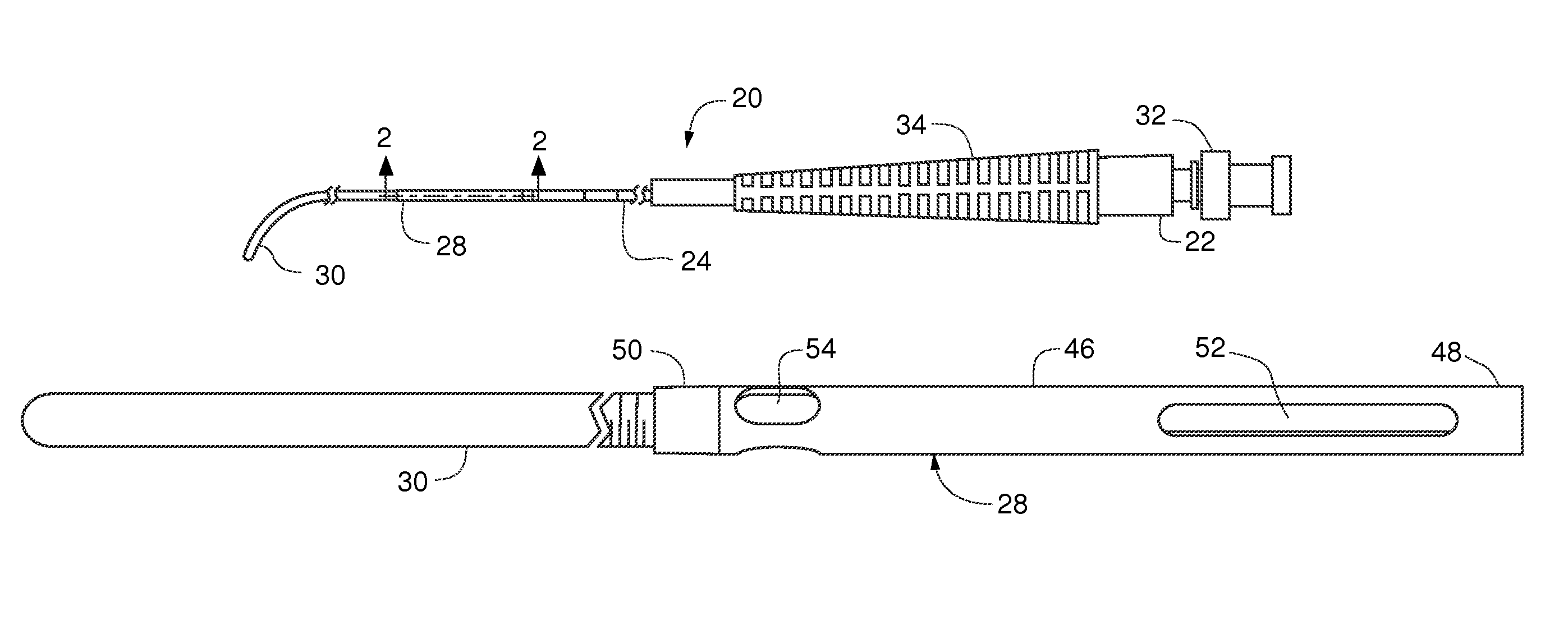
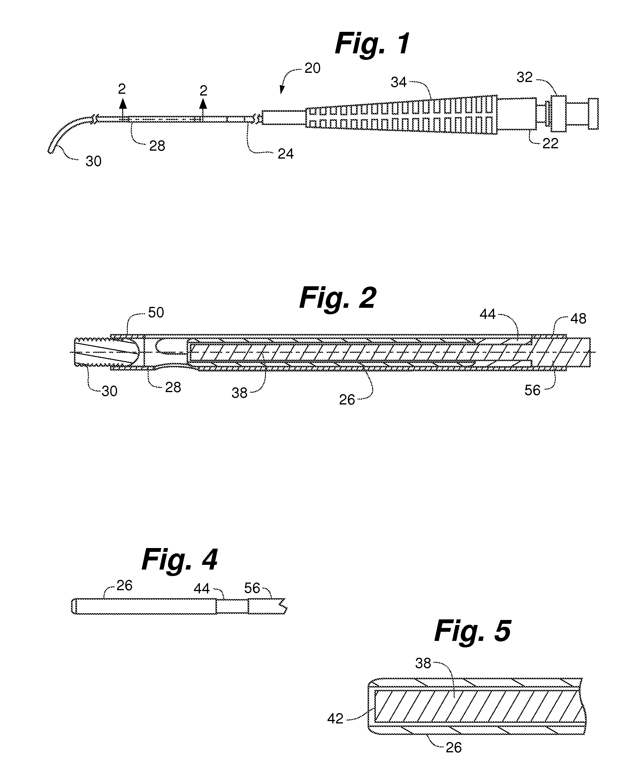
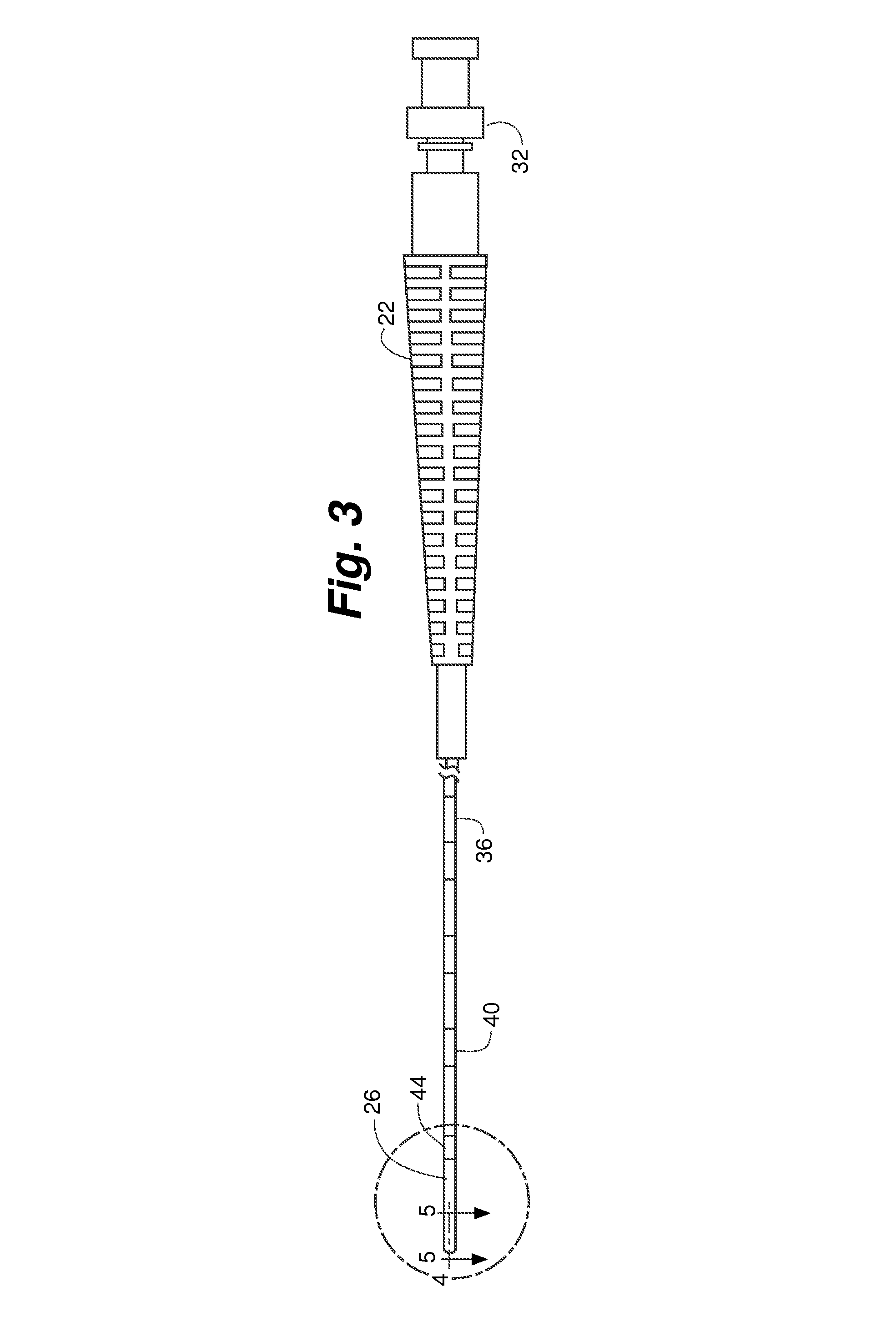
[0034]Referring particularly to FIGS. 1 and 2, guidewire tip laser fiber 20 in accordance with the present invention, generally includes fiber hub 22, optical fiber 24, tip shield 26, tip sleeve 28 and guidewire tip 30. Starting from the most proximal end of guidewire tip laser fiber 20, in an example embodiment, fiber hub 22 is coupled to and surrounds optical fiber 24. The distal end of optical fiber 24 is surrounded by tip shield 26. Tip shield 26 is surrounded by tip sleeve 28, which terminates in guidewire tip 30.

[0035]Referring to FIGS. 1, 3 and 7, fiber hub 22 is generally conventional in structure and includes coupler 32 and strain relief 34. Coupler 32 is adapted to couple fiber hub 22 to a console laser source (not shown). Coupler 32 and strain relief 34 surround the proximal end of optical fiber 24. Coupler 32 can be a standardized connector such as an SMA-905 connector for connection to a laser source console (not shown).

[0036]In one aspect of the invention, optical fibe...


PUM


Abstract

A device for application of energy within a tubular bodily structure including an optical fiber couplable to a source of laser energy and a guidewire tip. The optical fiber has a laser emitting portion remote from the source of laser energy and a distal end. The guidewire tip is operably secured to the optical fiber and extends distally outwardly away from the distal end of the optical fiber. The guidewire tip assists in advancing the device through the tubular bodily structure.

Description

FIELD OF THE INVENTION[0001]The present invention relates generally to the field of surgical instruments utilizing light application via optical fibers placed within the body. More particularly, the present invention relates to endovenous laser therapy of the peripheral veins, such as greater saphenous veins of the leg, for treatment of varicose veins.BACKGROUND OF THE INVENTION[0002]Varicose veins are enlarged, tortuous and often blue in color and commonly occur in the legs below the knee. Varicose veins are the most common peripheral vascular abnormality affecting the legs in the United States. Varicose veins often lead to symptomatic venous insufficiency. Greater saphenous vein reflux is the most common form of venous insufficiency in symptomatic patients and is frequently responsible for varicose veins in the lower leg. This occurs in about 25% of women and about 15% of men.[0003]All veins in the human body have valves that when functioning properly, open to allow the flow of bl...

Claims


Application Information

Patent Timeline
Patent Type & Authority Patents(United States)
IPC IPC(8): A61B18/18
CPCA61B18/22A61B18/245A61B2017/22045
Inventor ZINN, KENNETHWELCH, JEFFROOT, HOWARD
Owner TELEFLEX LIFE SCI LTD
Why Eureka
Try Eureka