Device for forging bush-shaped objects and a forged part produced therewith

a technology for forging bush-shaped objects and forged parts, which is applied in the direction of manufacturing tools, forging/hammering/pressing machines, transportation and packaging, etc., can solve the problems of limiting the life of the lower form mandrel and the external form ring, and the method of this type of forging is energy-consuming,

Inactive Publication Date: 2012-11-06
GESENKSCHMIEDE SCHNEIDER GMBH
View PDF25 Cites 2 Cited by
  • Summary
  • Abstract
  • Description
  • Claims
  • Application Information

AI Technical Summary

Benefits of technology

[0012]These disadvantages of the prior art are avoided by the device of the present invention which has a long service life and achieves sleeve-shaped forged parts having thin walls, and a long piston skirt.
[0018]Temperature control is essential when having to form hot parts. It is important that the temperature of the hot formed part is quickly and if possible regularly conducted inside the tool so that cold work hardening of the new form takes place and distortion of the component by uncontrolled temperature changes during the cooling process outside the form is avoided. According to the present invention, the internal form mandrel is provided with a high mass and is disposed inside the tool so that it has a tendency to cool more slowly than the other tool components.
[0020]A special feature of the present invention results from the interaction between the lifting and the extraction unit. Specifically, because a negative extraction cone alpha angle is provided inside the cavity of the upper form mandrel, the forged part is reliably lifted from the tool. The back-sliding of the forging blank into the forging form is hindered by the lower ejector which can be activated by the clamping base. By interaction between the upper and lower ejector, deep ejection marks and shape distortions can be avoided by a unilaterally acting force.
[0028]By the constant material flow having a constant velocity, enabled according to the present invention, a form filled to its smallest radius is produced, and as a consequence a forged part coming up to requested dimensions is produced. In this way, forging mistakes and many reworks can be avoided.
[0029]Before the placement of the preform it is preferred that at least one internal wall of the form is coated with a lubricant or releasing agent by which the material flow is facilitated and the ejection of the forged part facilitated.
[0031]Because the tool has a deep forging cavity with a minimal forging die chamfer and a cooled internal area and amoring, surprisingly the need of a second forging step for sleeve-shaped parts with a proportion of length to the external diameter of 0.5 m:1, is obviated, which reduces very much production time and costs.

Problems solved by technology

A method of this type is energy-consuming because at least two forging stations must be provided.
A further problem relating to the forging of sleeve-shaped parts in forging devices having cavity is the lifetime of the tools.
Deep cavities, long flow distances, high pressure inside the tools, and rapid cooling by application of lubricants, all limit the life time of the lower form mandrel and the external form ring, or forging sleeve.
A replacement or a rework of the tool and its parts causes downtime during the production process which makes the execution of the method more costly.
Tools are expensive and must be put available for production with minimum downtime caused by the need to repair or replace them.

Method used


Image

  • Device for forging bush-shaped objects and a forged part produced therewith
  • Device for forging bush-shaped objects and a forged part produced therewith
  • Device for forging bush-shaped objects and a forged part produced therewith

Examples


Embodiment Construction

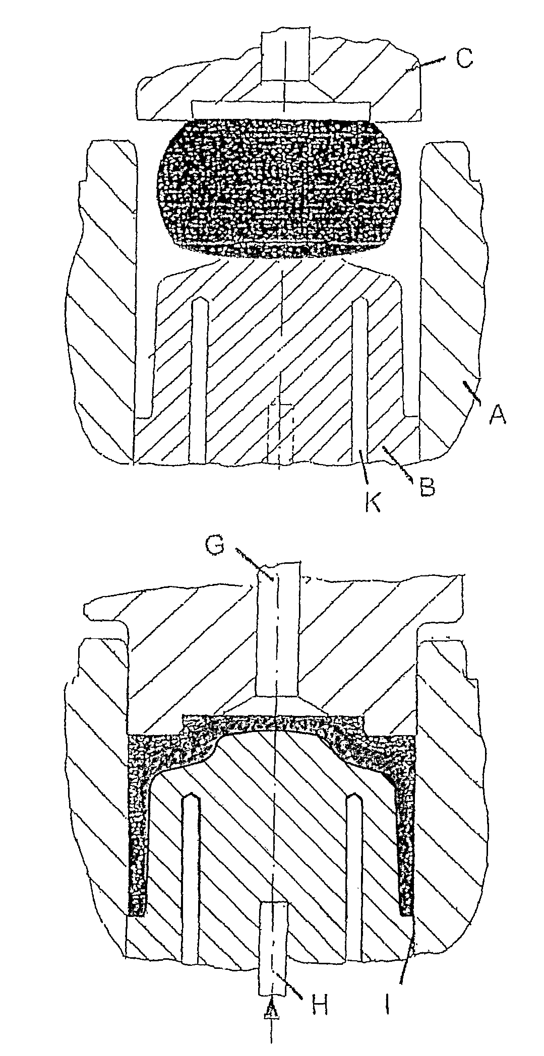
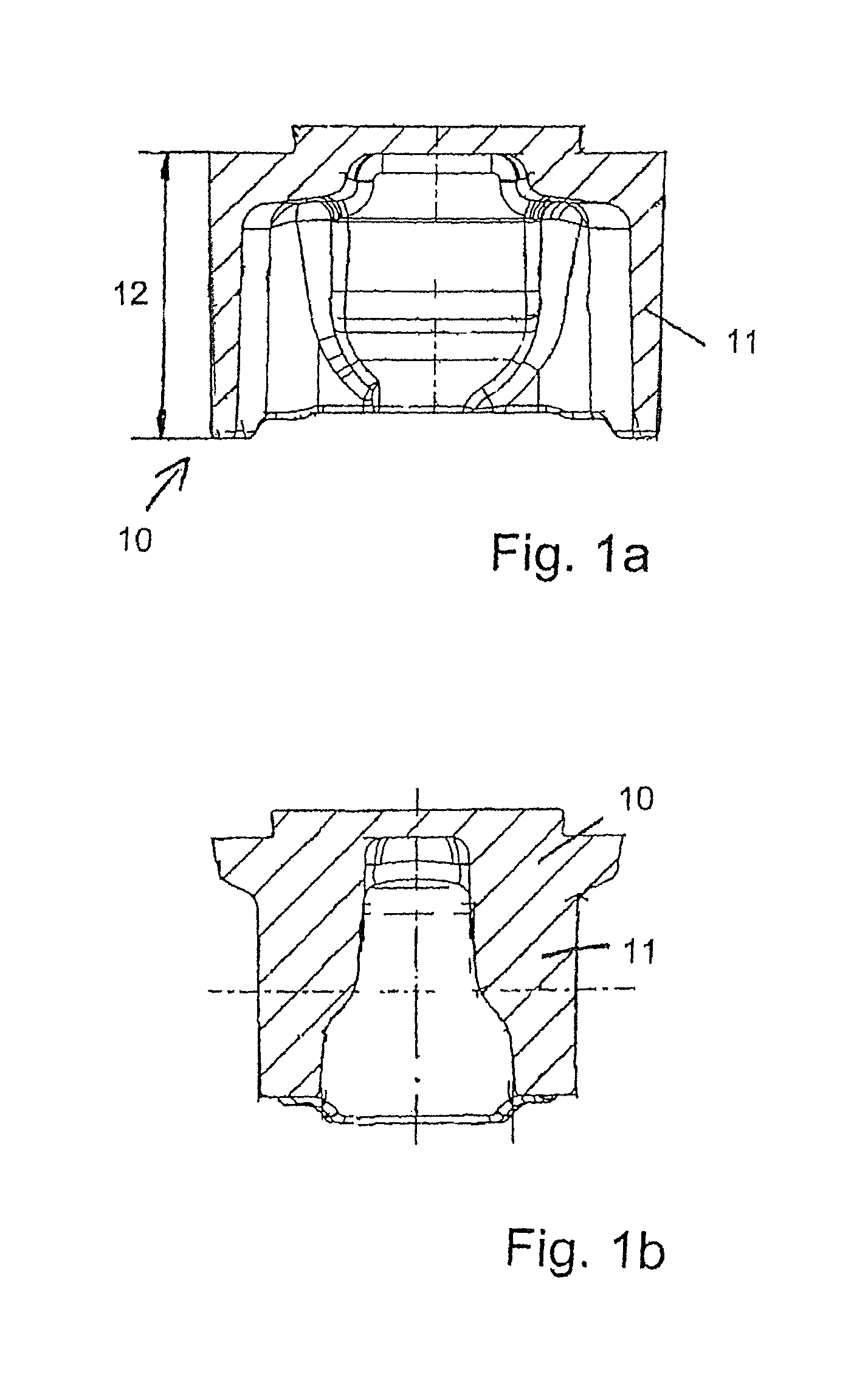
[0040]In FIG. 1 there is a sleeve-shaped forged part, in this case a piston 10 for a combustion engine, produced according to the present invention. This type of piston for combustion engines is made of 42CrMo4 steel and has for instance the following dimensions: the piston skirt 14 is at least 0.5 longer than the external diameter of the piston, of approximately 135 mm. The thickness of the lateral wall of the piston 11 is of approximately ⅙ of the external diameter of the piston. If it is a typical engine piston for combustion engines made of 42CrMo4, the piston skirt length is 60 to 85 mm, the thickness of the lateral wall of the piston between 6 and 10 mm, and the external diameter of the piston is between 115 and 140 mm. In further embodiments, e.g. a piston 10 for ship engines or drive motors for energy production plants according to the material, there are also other common dimensions, as it is known to the person skilled in the art of every branch. In this context, the speci...


PUM

PropertyMeasurementUnit
wall thicknessaaaaaaaaaa

Abstract

A device and method are provided for forging sleeve-shaped parts such as pistons. The device includes a form with: an upper form mandrel (C); an outer form ring (A); a lower form mandrel (B); an ejector device with an upper ejector (G) for ejection through the upper form mandrel (C); a lower ejector (H) for ejection through the lower form mandrel (B). Optional support devices for the form include a lower reinforcement ring (D) for the lower region of the outer form ring (A), a form mandrel housing (F) for the upper region of the outer form ring (A), and a clamping base (E) to support the lower form mandrel (B), by means of which the lower ejector (H) may be operated. The device and method advantageously facilitates the manufacture of pistons having a long skirt length and a minimal wall thickness.

Description

BACKGROUND OF THE INVENTION[0001]1. Field of Invention[0002]The invention relates to a device for the forging of sleeve-shaped objects like steel pistons, a method for the production of sleeve-shaped forgings and forgings produced according to the method.[0003]2. Description of Related Art[0004]Sleeve-shaped forgings are often produced from forgings of iron alloys, primarily steels. Such forgings are at least partially hot forged. A very common application of this type of sleeve-shaped parts is that of pistons for combustion engines. Although the invention is explained the context of the production engine pistons, these types of sleeves are also used in many other applications so that the present invention is generally applicable to all sleeve-shaped components made of forgeable material.[0005]In the prior art, pistons for combustion engines are forged in two steps, wherein a blank piston is inserted into a die having a pre-cavity to produce a semi-finished element in a first step. ...

Claims


Application Information

Patent Timeline
Patent Type & Authority Patents(United States)
IPC IPC(8): B21K1/42B21D53/26
CPCB21J5/02B21J13/03B21K21/02B21K1/18Y10T29/49453
Inventor SCHMITZ, ERNST-PETERKOLBE, PETER
Owner GESENKSCHMIEDE SCHNEIDER GMBH
Why Eureka
Try Eureka