Rail gun launcher

a launcher and rail technology, applied in the direction of launching weapons, white arms/cold weapons, dynamo-electric components, etc., can solve the problems of extremely high current required to be generated over a very short period of time, extremely high current required, and difficult to achieve, and achieves simple structure, efficient acceleration of armature, and elimination of inductive losses

Inactive Publication Date: 2012-11-06
LU WEIMIN
View PDF31 Cites 36 Cited by
  • Summary
  • Abstract
  • Description
  • Claims
  • Application Information

AI Technical Summary

Benefits of technology

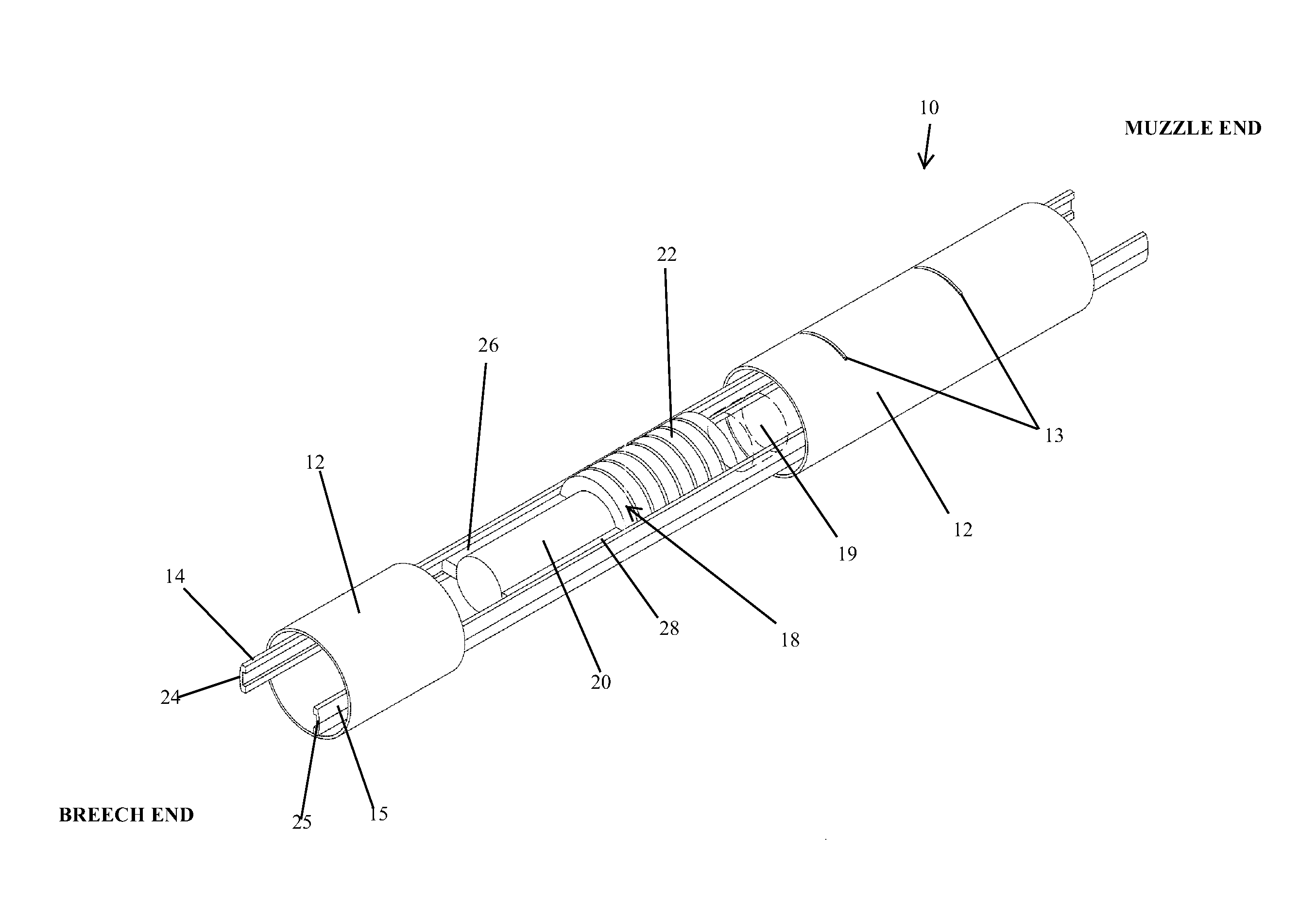
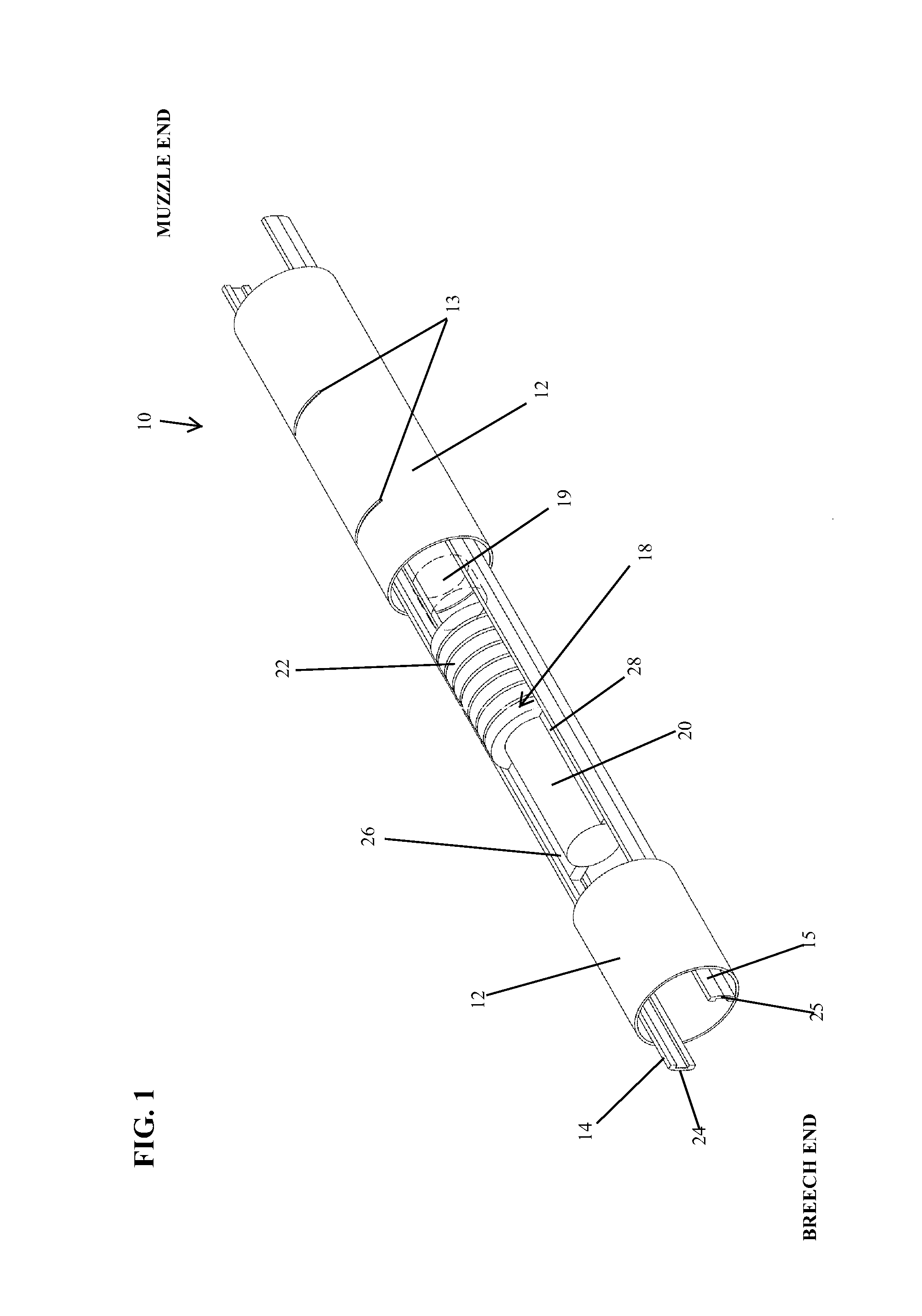
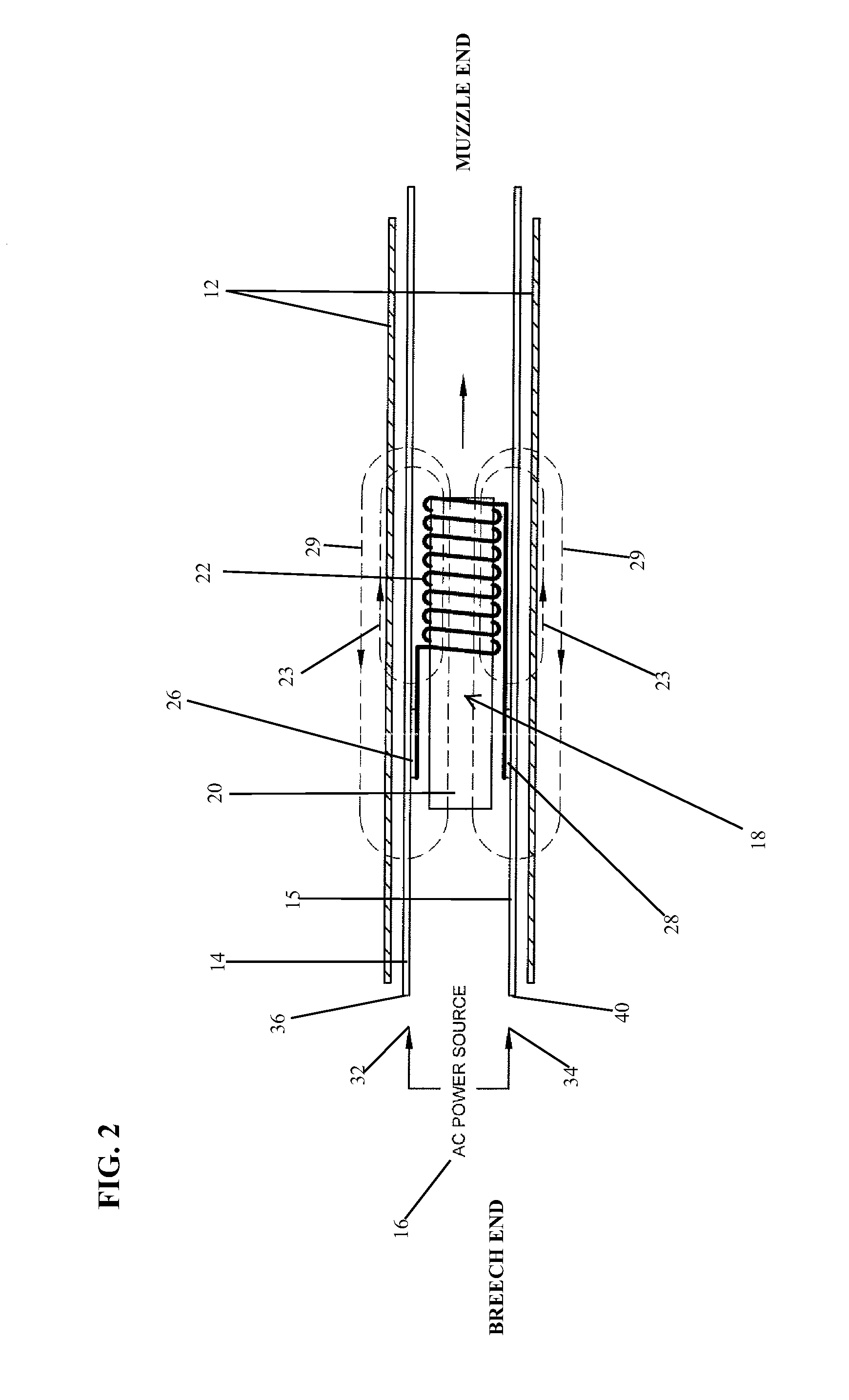
[0020]According to a first aspect and feature of the present invention, a rail gun launcher is provided for use in accelerating a projectile to hypervelocity (a velocity approximately 3,000 meters per second or greater), the rail gun launcher comprising: an electric power source; a conductive rail device including two members disposed in spaced, substantially parallel relation to each other and operatively connected to the power source; a movable armature operatively connected to the rail device for thereby forming a flowpath for current from the power source; and a non-magnetic, conductive, stationary barrel disposed coaxially with the movable armature and fixed along substantially a full length of the rail device, and the barrel is spaced from the rail device. The armature includes an elongate magnetic core and a multi-turn coil surrounding a portion of the magnetic core.
[0021]Such rail gun launcher according to the first aspect and feature of the present invention is very advantageous because it efficiently accelerates the armature, which may also be the projectile, to hypervelocity by induced magnetism with a relatively simple structure not involving commutation or switching devices (hence eliminating the inductive losses associated with such devices). The arrangement of the power source, rail device and armature creates a source magnetism when current flows through the multi-turn coil of the armature, and an equilibrium point for the source magnetism corresponds to an axial middle point of the multi-turn coil. On the other hand, because the conductive barrel is disposed coaxially with the armature, this creates a reversing induced current on the barrel, which in turn creates an induced magnetism having an equilibrium point which corresponds to an axial middle point of the elongate armature core. The equilibrium points for the source and induced magnetism are thus spaced each other. Further, the reversing induced current on the conductive barrel flows in the opposite direction of the current from the power source flowing through the multi-turn coil, and such opposite direction current flows repel each other, thereby continuously accelerating the armature along the rail device because the conductive barrel (as well as the rail device) is fixed. Because the multi-turn coil is in constant/continuous contact with the rails, the magnetic fields are constantly being generated, thereby accelerating the armature along the entire length of the barrel and rail device.
[0022]Moreover, since the rail gun launcher according to the first aspect and feature of the present invention includes the armature that includes the multi-turn coil, the rail gun

Problems solved by technology

While conventional rail guns are in principle very simple, they have several known disadvantages, making them practically difficult.
One known disadvantage is that, since the conventional rail gun involves only a single turn construction with the rails and armature, an extremely high current DC power source is required.
A related disadvantage is that the extremely high current is required to be generated over a very short period of time.
Without such a high current generated over such a short period of time, the armature would fail to be launched at an appropriate velocity.
A power source which can generate such a high amount of current over such a short period of time is both large in size and expensive.
Another disadvantage is that since the armature must be in constant physical contact and electrical conductivity with the rails to let electric current flow as the armature is being launched, large amounts of heat are generated between the moving armature and the rails which burns the rails thereby causing significant and rapid wear of the rails.
That very little movement creates a little gap in the contact between the armature and the rails, and the little gap causes arcing which creates the tremendous heat that destroys the rails.
Thus, conventional rail guns can only be used for a single operation or a small number of applications due to the damage to the rails caused by launching of the armature.
One manner of avoiding burning of the rails via friction heat is use of plasma arcing, but plasma arcing generates even greater heat so that it is not an effective solution to the problem.
Another disadvantage of conventional rail guns is that, because the armature and two rails are connected in a series-type connection electrically, the heat loss on the rails increases while the armatures, which is only a small fraction of the length of the rails, moves along the rails from breech to muzzle.
However, since the s

Method used


Image

  • Rail gun launcher
  • Rail gun launcher
  • Rail gun launcher

Examples


example 1

[0057]As an example of the embodiment shown in FIGS. 1-2, in calculations comparing the present invention with a conventional rail gun, with an extended length for the gun rails and without accounting for air friction, in an ideal scenario wherein there is no friction, the magnetic force F can be calculated using the Lorentz equation, which is reformatted below as Equation B, in SI units,

F=L*I*B*N  (Equation B)

wherein the magnetic force (F) is measured in Newtons, the length (L) is measured in meters, the current (I) is measured in amperes, the magnetic field (B) is measured in Tesla, and N is the number of turns in the coil. In the present invention, if only one-tenth ( 1 / 10) of the current (I) is used, with one hundred (100) turns of the coil, then the magnetic force (F) is ten (10) times greater (F=(I / 10)*B*100)=I*B*10) than in the conventional single turn rail gun. In other words, if we have a one hundred (100) turn coil in the present invention, we can achieve ten (10) times mo...

example 2

[0058]As en example of the embodiment described above in FIGS. 4 and 5, in (again) an ideal scenario wherein there is no friction, the magnetic force F can be calculated using the Lorentz equation, which is reformatted below as Equation B, in SI units,

F=L*I*B*N  (Equation B)

[0059]wherein the magnetic force (F) is measured in Newtons, the length (L) is measured in meters, the current (I) is measured in amperes, the magnetic field (B) is measured in Tesla, and N is the total turns in the coil. If the projectile is 0.1 meters in diameter, then the length (L) is 0.1 multiplied by Π (pi=approximately 3.14) which is 0.314 meters. Assuming that the current (I) is 1000 amps and the magnetic field (B) is 0.5 Tesla, then the coil would be made using 1000 turns. Thus, the magnetic force would be F=L*I*B*N=0.314*1000*0.5*1000=157,000 Newtons. If the projectile weighs four (4) kilograms, then the acceleration force (A)=Force / mass (F / m)=157,000 / 4=39,250 meters per second squared. Thus, if the pro...


PUM


Abstract

A rail gun launcher consists of an armature where a magnetic core with a multiple turn conductive coil, two parallel conductive rails on which terminals of the coil contact and slide, and a non-magnetic conductive barrel enclosing the rails and the armature. The coil partially encloses the magnetic core to shift magnetic equilibrium. When an AC power source is connected to the rails, the coil generates a source magnetism around the coil as well as an induced magnetism on the conductive barrel in an opposite direction through the magnetic core. The source magnetism and the induced magnetism are shifted in magnetic equilibrium and in opposite direction thereby repelling the armature forward. This repulsive force travels with the armature and is continuous from breech to muzzle and propels the armature forward to a high velocity without control circuitry or commutation.

Description

BACKGROUND OF THE INVENTION[0001]1. Field of the Invention[0002]The present invention relates to an improved rail gun launcher having much greater efficiency and durability in comparison to conventional rail gun launchers. More particularly, to such a rail gun launcher with a unique multi-turn armature structure which can be continuously accelerated to a hypervelocity (a velocity approximately 3,000 meters per second or greater) in a very efficient manner involving much less power consumption and a comparatively smaller power source than has been previously possible, and wherein the overall structure of the rail gun launcher is relatively uncomplicated.[0003]2. Description of the Background Art[0004]Known electromagnetic accelerators have been designed to accelerate and launch projectiles at high velocities. An example of such an electromagnetic accelerator is a conventional rail gun comprising parallel conductive rails (which are fixed in position) and a conductive armature (or pro...

Claims


Application Information

Patent Timeline
IPC IPC(8): F41B6/00
CPCF41B6/003F41B6/006
Inventor LU, WEIMIN
Owner LU WEIMIN
Why Eureka
Try Eureka