Tissue processor for treating tissue samples

a tissue processor and tissue technology, applied in mixers, biochemistry apparatus and processes, mixers, etc., can solve the problems of low stirring effect, small force transmission, and insufficient adhesive force of magnets, and achieve good stirring effect and high force

Active Publication Date: 2012-11-06
LEICA BIOSYST NUSSLOCH
View PDF5 Cites 2 Cited by
  • Summary
  • Abstract
  • Description
  • Claims
  • Application Information

AI Technical Summary

Benefits of technology

[0011]The invention is characterized in that the stirring body has a first magnet the north pole of which faces the underside of the stirring body and thus the drive unit and the south pole of which faces away from the underside of the stirring body and thus from the drive unit, and in that the stirring body has a second magnet the south pole of which faces the underside of the stirring body and thus the drive unit and the north pole of which faces away from the underside of the stirring body and thus from the drive unit. As viewed from the direction of the drive unit, both magnets together appear as one big magnet having one north pole and one south pole. Hereby it is achieved that a high force can be transmitted from the drive unit via the magnetic field to the stirring body so that the stirring body can be operated at a high speed of rotation. As a result thereof, it can be achieved that the liquid is stirred well. Further, it is hereby achieved that due to the high force which can be transmitted from the drive unit to the stirring body, the stirring body does not have to be started-up slowly with a ramp, but can be immediately operated at full speed. Thus, also in the case of higher viscosity media the required magnetic adhesion is not lost. It is advantageous if the stirring body comprises at least three vanes. Hereby an even better stirring effect is achieved.
[0018]The stirring body preferably comprises an integrally formed basic body which comprises the vanes of the stirring body and two receiving elements, wherein one of the two magnets each is accommodated in the receiving elements. The two receiving elements each have an opening for insertion of the magnets. After insertion of the magnets, the openings of the receiving elements are preferably closed in a water-tight manner with the aid of one closing cap each. For this, the closing caps are welded thereto in particular by means of ultrasonic welding or laser welding. By integrally forming the basic body it is achieved that no joints occur and thus weakenings of the component are prevented, as a result whereof in turn the life of the component is increased. By receiving the magnets within the receiving elements and the water-tight closing of the openings of the receiving elements it is achieved that the magnets do not come into contact with the liquid, and thus possibly damaging effects caused by the contact with the liquid, in particular with aggressive liquid, are prevented. The basic body is in particular made of polyoxymethylen (POM). POM is characterized on the one hand by a high chemical resistance to most liquids used, as well as by a high strength, hardness and stiffness. Thus, a long life of the component is achieved.

Problems solved by technology

When stir bars are used, it is disadvantageous that these move in an uncontrolled manner in the process chamber, that only a low stirring effect is achieved by the stir bars, and that only small forces can be transmitted from the drive unit of the magnetic stirrer to the stir bar.
What is disadvantageous with this embodiment is that, in this embodiment too, only a small force can be transmitted between the drive unit and the magnet, and thus no sufficient adhesive force of the magnets is given.
Further, it is disadvantageous that, with this design of the stirring body, a relatively long time is required in order to achieve the desired heat distribution.

Method used


Image

  • Tissue processor for treating tissue samples
  • Tissue processor for treating tissue samples
  • Tissue processor for treating tissue samples

Examples


Embodiment Construction

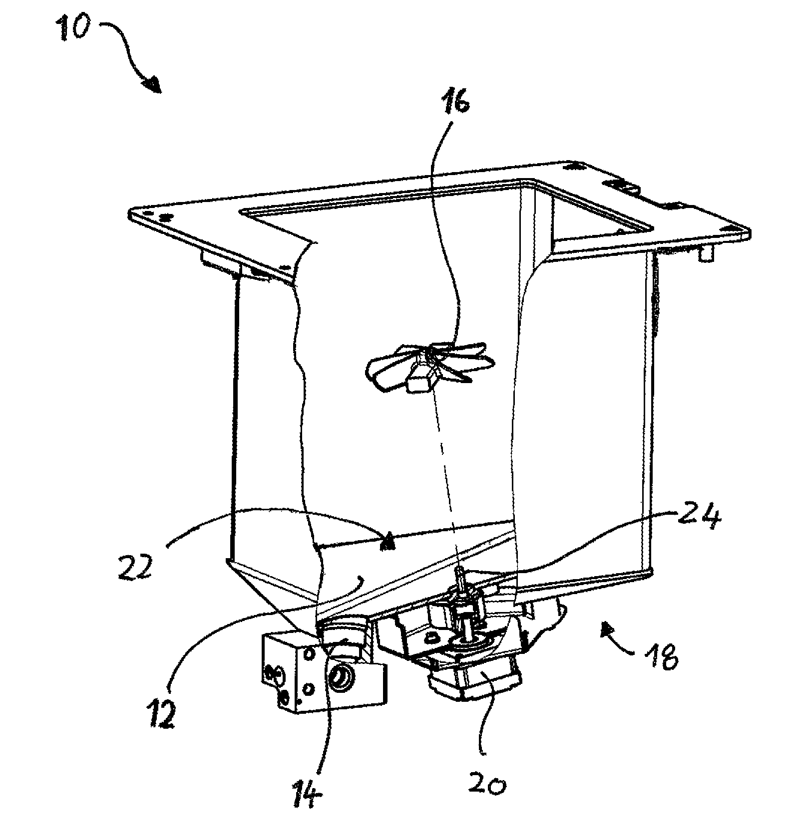
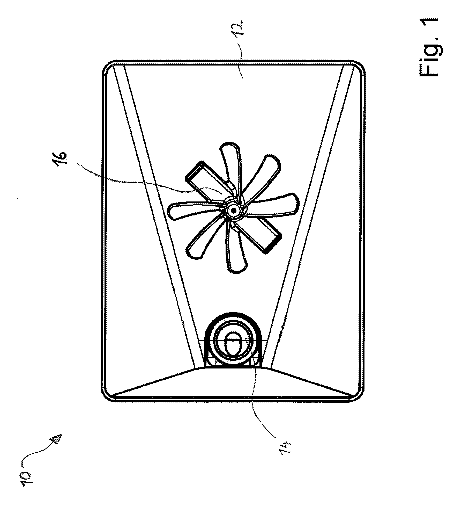
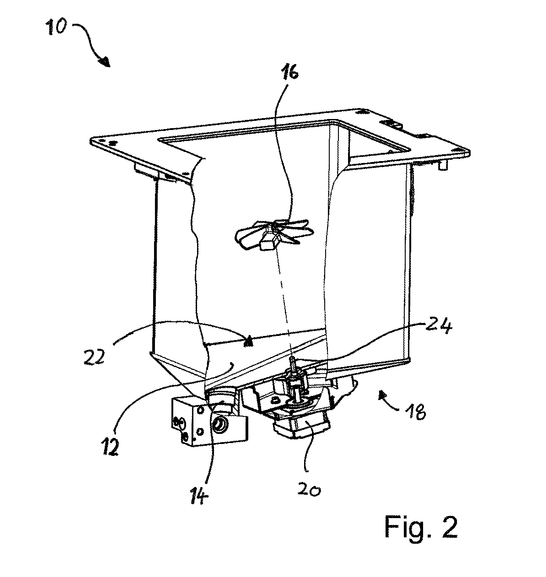
[0032]In FIG. 1 a top view of a process chamber 10 of a non-illustrated tissue processor is shown. The process chamber 10 is also referred to as retort. It comprises a bottom in which an outlet 14 is arranged through which a liquid contained in the process chamber 10 can be drained off. The tissue processor serves for the treatment of tissue samples with liquids in order to prepare the tissue samples for a later microscopic examination. For this, at least one liquid and at least one tissue basket in which the tissue samples are arranged are placed in the process chamber 10. In order to guarantee a uniform treatment of the tissue samples with the liquid it is necessary that there are homogeneous properties, in particular a homogeneous heat distribution, all over the liquid. In order to achieve this, the process chamber 10 is formed as a vessel of a magnetic stirrer, and a stirring body 16 is arranged within the process chamber 10. When the stirring body 16 rotates, the liquid contain...


PUM


Abstract

A tissue processor for treating tissue samples comprises a process chamber (10) in which the tissue samples can be treated with at least one liquid. The process chamber (10) is formed as a vessel of a magnetic stirrer. In the process chamber, a stirring body (16) for stirring the liquid is arranged, wherein the stirring body (16) comprises at least one magnet (40a, 40b) with the aid of which the stirring body (16) can be set in rotation by a drive unit (20) of the magnetic stirrer, and at least one vane (28a to 28f) by which the liquid to be stirred is stirred when the stirring body (16) rotates. According to a first aspect of the invention, the stirring body (16) has at least three vanes (28a to 28f), according to a second aspect of the invention, the stirring body (16) has at least one further magnet (40b). The north pole (46) of the one magnet (40a) and the south pole (50) of the further magnet (40b) face the drive unit (20).

Description

CROSS REFERENCE TO RELATED APPLICATIONS[0001]This application claims priority of German patent application number 10 2009 050 048.0 filed Oct. 21, 2009, the entire disclosure of which is incorporated by reference herein.FIELD OF THE INVENTION[0002]The invention relates to a tissue processor for treating tissue samples. The tissue processor comprises a process chamber which has a bottom and in which the tissue samples can be treated with at least one liquid. Moreover, the tissue processor comprises a drive unit which is arranged on a side of the bottom facing away from the process chamber. The process chamber is formed as a vessel of a magnetic stirrer. In the process chamber, a stirring body for stirring the liquid contained in the process chamber is arranged, which stirring body can be set in rotation in a contact-free manner with the aid of the drive unit. The stirring body comprises at least one vane by which the liquid to be stirred is stirred when the stirring body is rotated.B...

Claims


Application Information

Patent Timeline
Patent Type & Authority Patents(United States)
IPC IPC(8): A61B10/00
CPCB01F7/162B01F7/22B01F13/0827B01F13/0872C12M45/02B01F7/00033B01F27/053B01F27/808B01F27/91B01F33/453B01F33/4535
Inventor HABERKORN, CLAUS
Owner LEICA BIOSYST NUSSLOCH
Why Eureka
Try Eureka