Food processing stirrer

A technology for food processing and mixers, which is applied to mixer accessories, mixers with rotating mixing devices, mixers, etc., can solve the problems of general mixing effect of mixing rods, single mixing form, and insufficient mixing, and achieves increased mixing effect. Improve mixing efficiency and increase the effect of diversion effect

Inactive Publication Date: 2019-04-02
嘉兴市爵拓科技有限公司
View PDF0 Cites 5 Cited by
  • Summary
  • Abstract
  • Description
  • Claims
  • Application Information

AI Technical Summary

Problems solved by technology

The existing mixers used in the food field have a single structure, and only rely on the main shaft to drive the parallel stirring rods for stirring. The stirring and flow speed at the bottom of the barrel will be affected to a certain extent, and it is easy to cause problems such as uneven stirring and layering at the top and bottom At the same time, the stirring effect of the stirring rod with smooth outer surface is average. During the stirring process, the raw materials are easily thrown to the top of the barrel and bonded to it, resulting in incomplete stirring. In addition, usually only one kind of stirring blade is set on the stirring shaft. Due to the single stirring form, it is easy to cause uneven stirring

Method used


Image

  • Food processing stirrer
  • Food processing stirrer
  • Food processing stirrer

Examples


Embodiment 1

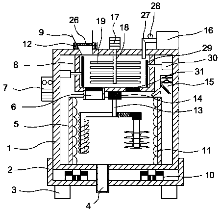
[0024] Such as Figure 1-3As shown, the scheme adopted by the present invention to achieve the above object is: a food processing mixer, comprising a housing 1, the side wall of the housing 1 is provided with a control panel 7, the top of the housing 1 is provided with a crushing box 8, and the lower end of the crushing box 8 is A stirring box 5 is provided, and push plates 29 are provided on both sides of the crushing box 8, and the surface of the pushing plate 29 is connected to the output end of the electric push rod 30 provided on the top of the housing 1, and a weight sensor 31 is provided on the bottom side of the crushing box 8 , by setting a control panel on the side wall of the housing, it is used to control the intelligent operation of each power component in the device and improve the intelligent level of the device. The weight sensor installed at the bottom of the box detects that the weight of food accumulated on one side of the crushing box exceeds the preset val...

Embodiment 2

[0032] Such as Figure 4-5 As shown, the optimization scheme of this embodiment on the basis of Embodiment 1 is: the inner wall of the stirring box 5 is evenly distributed with spoilers 11, and the upper part of the stirring box 5 is provided with a stirring motor a14 installed at the bottom of the crushing box 8, stirring The output end of the motor a14 is connected to the main shaft 13, one side of the main shaft 13 is connected with the L-shaped stirring rod 137, and the vertical side of the L-shaped stirring rod 137 is evenly arranged on one side near the stirring box 5 with arc-shaped scraping bars 136, and the L-shaped stirring rod 137 is vertical A stirring wire 131 is provided on the other side of the side. A stirring motor a is installed above the mixing box and installed at the bottom of the crushing box. The output end of the stirring motor a is connected to the main shaft. By running the stirring motor a, the main shaft is rotated, which drives the L-shaped stirrin...

Embodiment 3

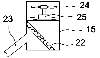
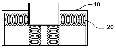
[0035] The working principle of the food processing mixer of the present invention is: put the food to be processed into the pulverizing box 8 from the discharge port 9, start the pulverizing motor 17 through the control panel 7 to drive the pulverizing pieces 19 on the rotating shaft to pulverize the food, and pulverize the pulverized food. The food falls into the mixing box 5 from the bulk material port 6 and stirs. When processing different foods, the water feeder 16 can be started to add water at a suitable temperature to the mixing box 5 for stirring. The dust collector 15 can Dust generated during the stirring process is adsorbed, and the anti-vibration base 10 plays a role of shock absorption during the crushing and stirring process.


PUM


Abstract

The invention discloses a food processing stirrer, which comprises a shell, wherein the side wall of the shell is provided with a control panel, a crushing box is arranged on the upper portion insidethe shell, a stirring box body is arranged on the lower end of the crushing box, pushing plates are arranged on the inner walls of both sides of the crushing box, the surface of the pushing plate is connected to the output end of an electric pushing rod arranged on the upper portion inside the shell, and one side of the bottom portion of the crushing box is provided with a weight sensor. Accordingto the present invention, the control panel is arranged on the side wall of the shell, and is used for controlling the intelligent operation of each power component in the device so as to improve theintelligent level of the device; the crushing box and the stirring box arranged in the shell are used for crushing and stirring the food; by arranging the weight sensor on the bottom portion of the crushing box, when the detected weight of the food accumulated on the side of the crushing box exceeds the preset value, the control panel starts the electric pushing rods to operate, and the pushing plates on both sides in the crushing box are pushed to the middle, such that the food accumulated on both sides are pushed to the middle portion of the crushing box to be crushed so as to increase thecrushing efficiency; and the food processing stirrer has advantages of simple structure and convenient operation, and is suitable for large-scale promotion.

Description

technical field [0001] The invention relates to the technical field of food processing, in particular to a food processing mixer. Background technique [0002] The food industry is the pillar industry of my country's national economy. Food machinery is an industry that provides equipment for the food industry. my country's food machinery industry began in the early 1950s when New China was established, mainly after the reform and opening up in the 1980s. The strength of the company has grown from scratch, from small to large, from weak to strong, from low to high, and gradually developed and improved from scratch. It has gone through nearly 60 years of glorious development. China's food machinery manufacturing industry It has been on the rise in recent years, food safety has become increasingly severe, and equipment replacement has become a major trend. Because of this, China's food machinery manufacturing industry will maintain growth for a long period of time in the future, ...

Claims


Application Information

Patent Timeline
Patent Type & Authority Applications(China)
IPC IPC(8): B01F13/10B01F15/00B01F7/16B01F7/26B01F3/20B02C18/10B02C18/24B02C18/22B02C23/10B01F23/70B01F27/93
CPCB02C18/10B02C18/2216B02C18/24B02C23/10B01F23/70B01F23/708B01F23/713B01F27/1152B01F27/192B01F27/80B01F27/93B01F33/831B01F35/12B01F35/20B01F35/184B01F35/188B01F35/187B01F2101/06
Inventor 乔元昊张广涛孟昭军
Owner 嘉兴市爵拓科技有限公司
Why Eureka
Try Eureka