Check patentability & draft patents in minutes with Patsnap Eureka AI!

Data acquisition system for test and measurement signals

a data acquisition and data technology, applied in data switching networks, frequency-division multiplexes, instruments, etc., can solve the problems of difficult processing and display of such high-rate data, and achieve the effect of facilitating the provision of pointers

Inactive Publication Date: 2012-11-06
C SPEED
View PDF4 Cites 31 Cited by
  • Summary
  • Abstract
  • Description
  • Claims
  • Application Information

AI Technical Summary

Benefits of technology

[0009]It is another object of the present invention to provide an improved system for acquisition of test and measurement data which enables sampling input signals up to 2 GS / s using an FPGA previously limited to sampling at 1 GS / s.
[0011]It is still a further object of the present invention to provide an improved system for acquisition of test and measurement data having a computer system which automatically selects for readout one of downsampled data or full resolution sample data from memory of an acquisition device to provide for a faster update rate of display to a user.
[0019]Preferably, the components for enabling the sampling, storage and readout of data, such as provided by the differential receivers, registers, memory controller, downsampler, generation of the two phase shifted clocking signals from a clock, and distribution of such signals to registers, are provided by a configured FPGA in the acquisition device. Using an FPGA, such as for example the Xilinx, Inc. Virtex-4 family FPGA having a 500 MHz internal clock, enables acquisition of input signals up to 2 GS / s in which the registers are operated in accordance with a two phase shifted clock signals derived from the internal clock of the FPGA.

Problems solved by technology

One drawback of viewing high rate signals is that readout, processing, and display of such high rate data is difficult with communication bandwidth bottlenecks between the acquisition device and the host computer system and hardware limitations of the host computer system.

Method used


Image

  • Data acquisition system for test and measurement signals
  • Data acquisition system for test and measurement signals
  • Data acquisition system for test and measurement signals

Examples


Embodiment Construction

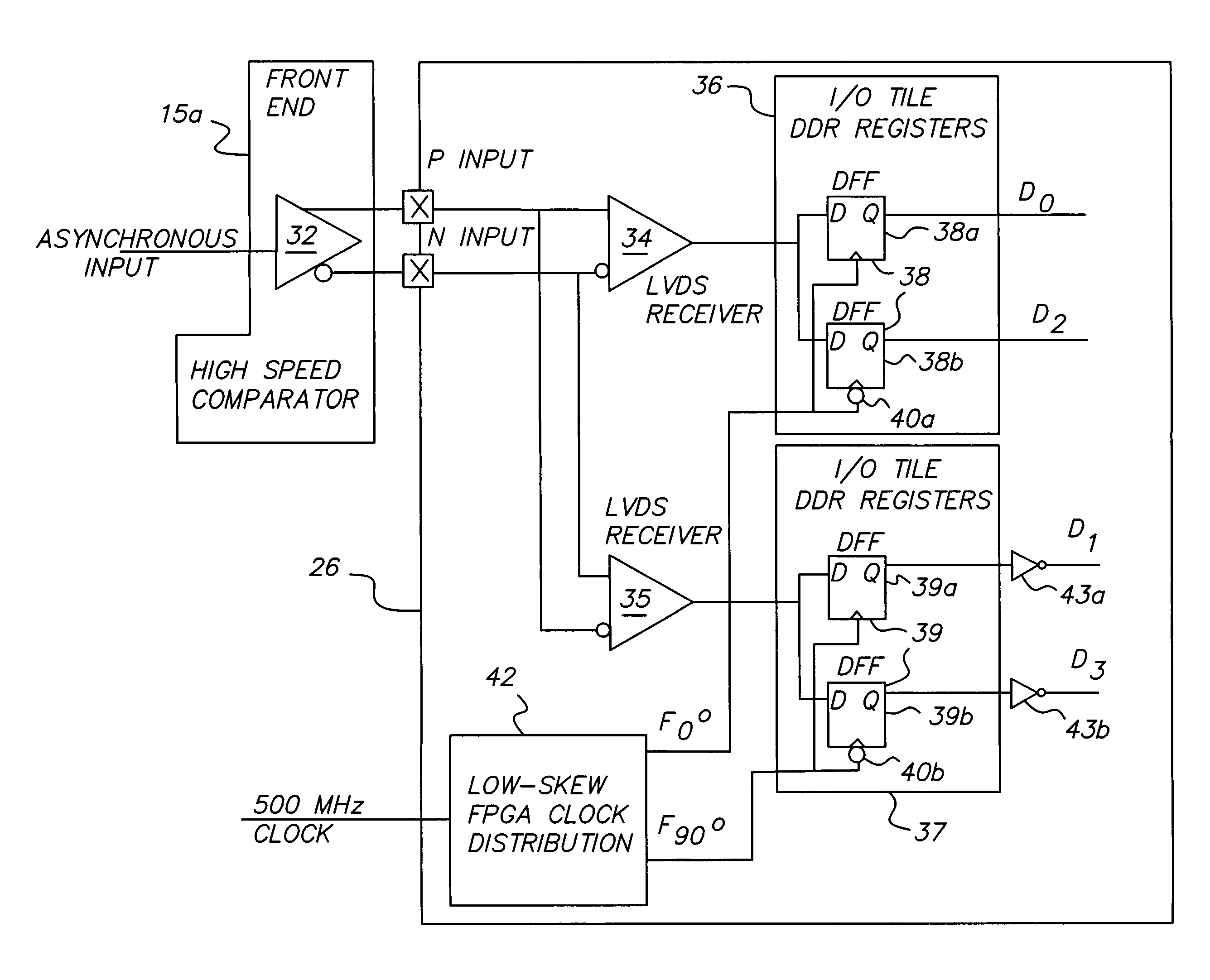
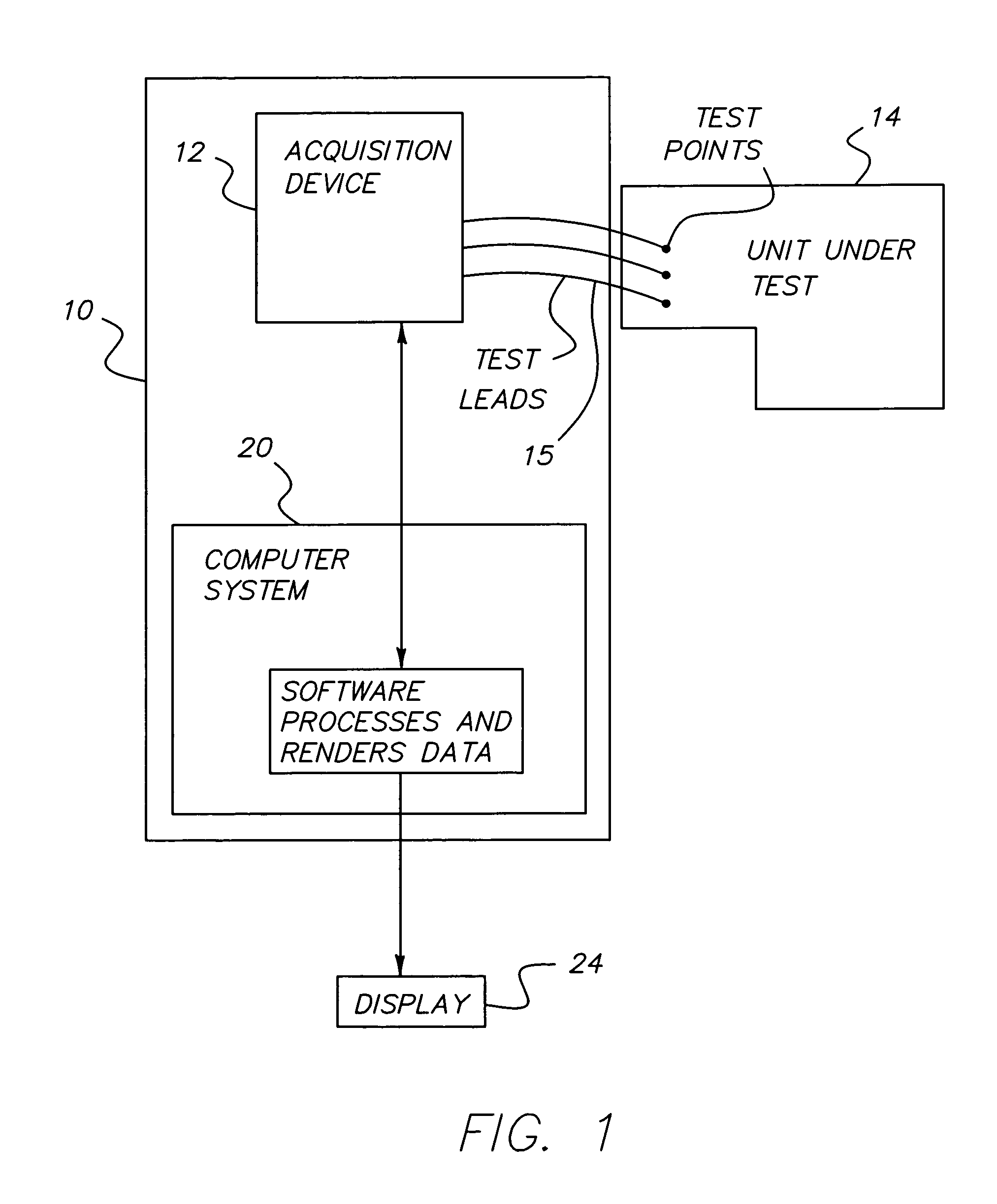
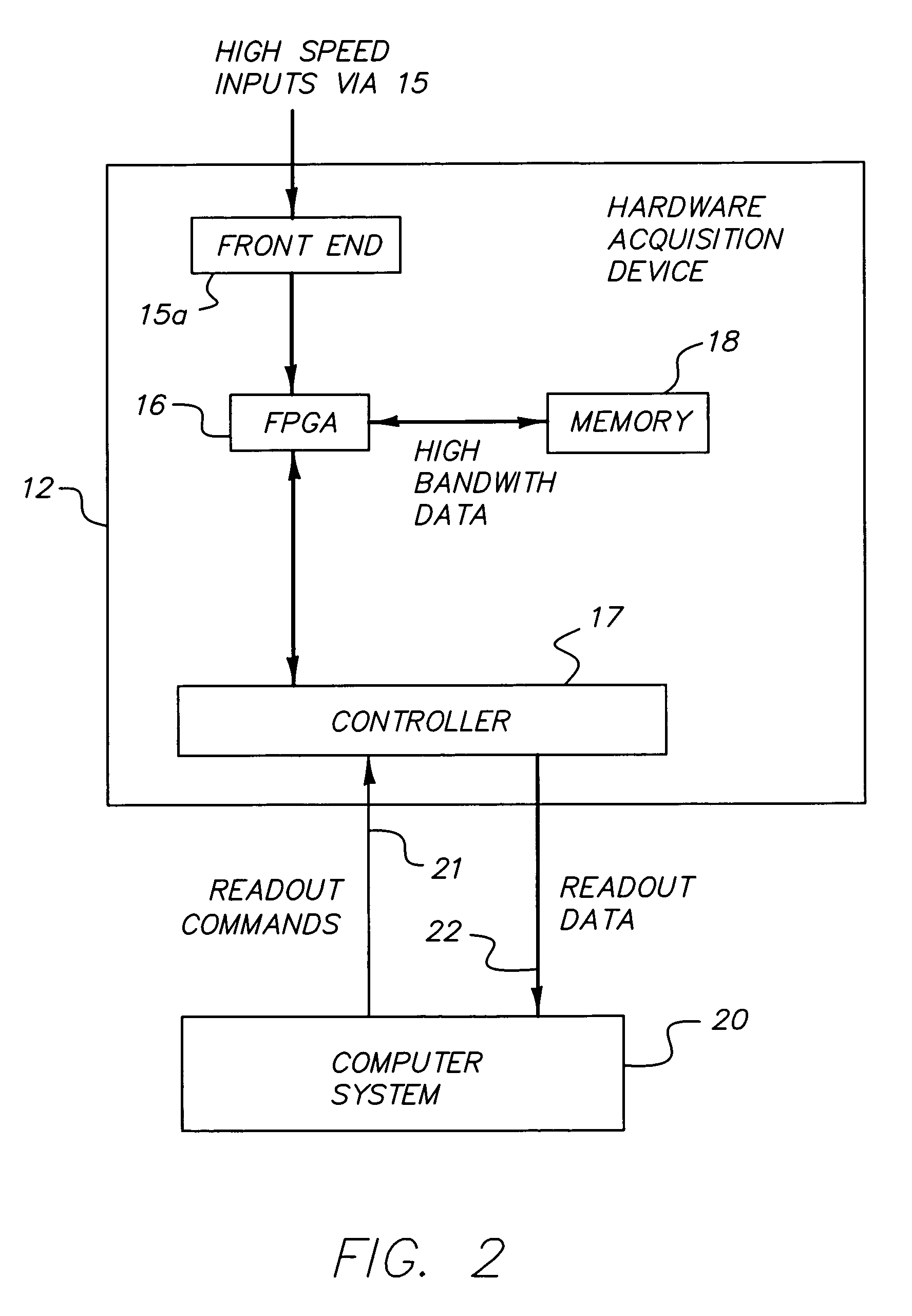
[0033]Referring to FIGS. 1 and 2, the system 10 of the present invention has an acquisition device 12, which receives multiple channels of electrical signals having amplitude or value over time from a device (unit or system) 14 under test, via test leads 15, and converts each of the electrical signals into digital data utilizing a front end 15a and a processing unit provided by an FPGA (field programmable gate array) 16 for storage in memory 18. A controller 17 in the acquisition device 12 provides an interface between the FPGA 16 and a host computer system 20, whereby computer system 20 may request data stored in memory 18 and controller 17 provides readout 22 of such data requested. The computer system 20 stores the received data in its memory (RAM or hard / optical drive) for rendering of the data by the computer system on display 24. Computer system 20 may represent a personal computer, work station, laptop computer, or other microprocessor based platform that is coupled to displa...


PUM


Abstract

A system having an acquisition device for acquiring test and measurement data and providing such data to a computer system for display of such data. For each input data signal, the acquisition device has two differential receivers of opposite polarity each having an output coupled to the input of different ones of two pairs of registers, resulting in four registers sampling the input data signal periodically at four different times in accordance with two clocking signals of different phase (phase shifted 90°) to provide a sampling rate four times the rate of the clocking signals. The resulting sample data is stored in memory of the acquisition device along with downsampled data representing a compressed, low resolution, version of the sample data which records toggling in the sample data notwithstanding such downsampling. The computer system can request readout of stored sample data and / or downsampled data during or after acquisition of sample data and downsampled data. The acquisition device preferably utilizes an FPGA to provide sampling, storage and readout of data stored in memory of the device. The FPGA may be reconfigurable in response to the computer system to provide one of different data acquiring modes selectable by a user.

Description

FIELD OF THE INVENTION[0001]This present invention relates to a system (method) for acquisition of test and measurement data and reading out the acquired data to a computer system, and relates particularly to a system for acquisition of test and measurement data capable of sampling up to a 2 Gigasamples per second (GS / s) input signal using a clock operating at 500 MHz. The invention is particularly suitable with a Virtex-4 family FPGA manufactured by Xilinx, Inc. of San Jose, Calif. Heretofore such Virtex-4 family FPGA with a clock speed of 500 MHz per second was configurable to acquire data rates only as high as 1 GS / s, while the present invention enables use of the same FPGA to achieve acquisition rates of 2 GS / s (i.e., 4×500 MHz clock speed). In addition, at the same time of acquisition of the sample data the acquisition device produces and stores in its memory downsampled data representing a compressed version of the sample data which records detected toggling in the sample data...

Claims


Application Information

Patent Timeline
IPC IPC(8): H04J3/14
CPCG01R13/0272G06F15/00
Inventor LOUISE, JUSTIN RALPHFRANCIS, KEVIN ROYHARRY, BRIAN DAVIDSHEPARDSON, BRYAN THOMAS
Owner C SPEED
Features
  • R&D
  • Intellectual Property
  • Life Sciences
  • Materials
  • Tech Scout
  • Unparalleled Data Quality
  • Higher Quality Content
  • 60% Fewer Hallucinations
Learn More