Power conversion driving circuit and fluorescent lamp driving circuit

a driving circuit and power conversion technology, applied in the direction of machines/engines, process and machine control, instruments, etc., can solve the problems of low conversion efficiency of electric power, failure of controller con operation, and inability to supply electric power more, so as to reduce the power consumption of the control circuit, avoid danger for users, and increase the convenience of users

Active Publication Date: 2012-11-13
GREEN SOLUTION TECH CO LTD
View PDF4 Cites 12 Cited by
  • Summary
  • Abstract
  • Description
  • Claims
  • Application Information

AI Technical Summary

Benefits of technology

[0011]Accordingly, an embodiment of the invention provides a power conversion driving circuit. The power conversion driving circuit is turned off when the load driven thereby is removed. Therefore, the power consumption by the control circuit is reduced when the abnormal state occurs in the power conversion driving circuit, and the danger to users is also avoided when they use the power conversion driving circuit. Moreover, after load replacing, the power conversion driving circuit is automatically re-started to increase users' convenience.
[0016]As a result, the electric power required for operating is stopped from being provided when the load circuit is removed, so that the control circuit is turned off due to the insufficiency of driving voltage. Accordingly, the power consumption by the control circuit is reduced. Moreover, when the load circuit is inserted again, the electric power required for operating is provided again. Therefore, the control circuit is automatically re-started, so that the capability to automatically re-start the power conversion driving circuit is also reached.

Problems solved by technology

However, electric devices in the circuit are large, so that the volume of the circuit is large, and the weight thereof is heavy, and further, conversion efficiency thereof is low.
Accordingly, the initial resistor R having a relatively large resistance is used to lower power consumption by the initial resistor R. However, when an abnormal event occurs in the circuit, no more electric power from the DC input voltage VIN is supplied to the to the AC output voltage VOUT, so that the transformer T2 and the diode D can not supply the electric power any more.
Moreover, the electric power transmitted through the initial resistor R is not enough to provide all of the electric power required by the controller CON while normally operating, so that the operation of the controller CON may fail.
When the driving voltage VDD has become lower than a voltage range which the controller CON can operate, the controller CON stops operating and further decreases the consuming power.
In the process, not only is life-span of the lamp shortened due to limitation of start cycles thereof, but also users may get an electric shock during lamp replacing if the users forget to turn off the power source.
Moreover, if the users turn off the power source first, and next turn on the power source after the lamp has been replaced with new one, the users may not get the electric shock during lamp replacing, but it is not convenient for the users and is different from the normal users' habits.
Accordingly, even though the lamp driving circuit may re-start the lamp in the SPS of the related art, not only is the life-span of the lamp shortened, but also using it may be dangerous to the users.

Method used


Image

  • Power conversion driving circuit and fluorescent lamp driving circuit
  • Power conversion driving circuit and fluorescent lamp driving circuit
  • Power conversion driving circuit and fluorescent lamp driving circuit

Examples


first embodiment

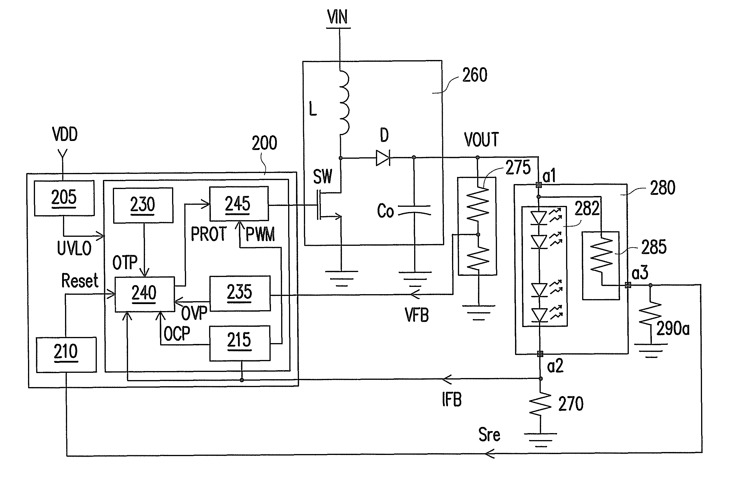
[0028]FIG. 3 is a schematic circuit of a power conversion driving circuit consistent with the invention. Referring to FIG. 3, the power conversion driving circuit includes a control circuit 200, a converting circuit 260, and a load circuit 280. The converting circuit 260 is a boost DC / DC converting circuit including an inductor L, a diode D, a switch SW, and an output stabilizing capacitor Co. The converting circuit 260 is configured to receive an input voltage VIN and converts the received input voltage VIN up to the output voltage VOUT. The load circuit 280 includes a light emitting diode (LED) module 282 and a load detecting unit 285. The LED module 282 is coupled to the converting circuit 260 to receive the output voltage VOUT through a first connecting terminal a1 of the load circuit 280, and the LED module 282 is grounded through a second connecting terminal a2 of the load circuit 280. The load detecting unit 285 includes a resistor. One terminal of the resistor is coupled to...

second embodiment

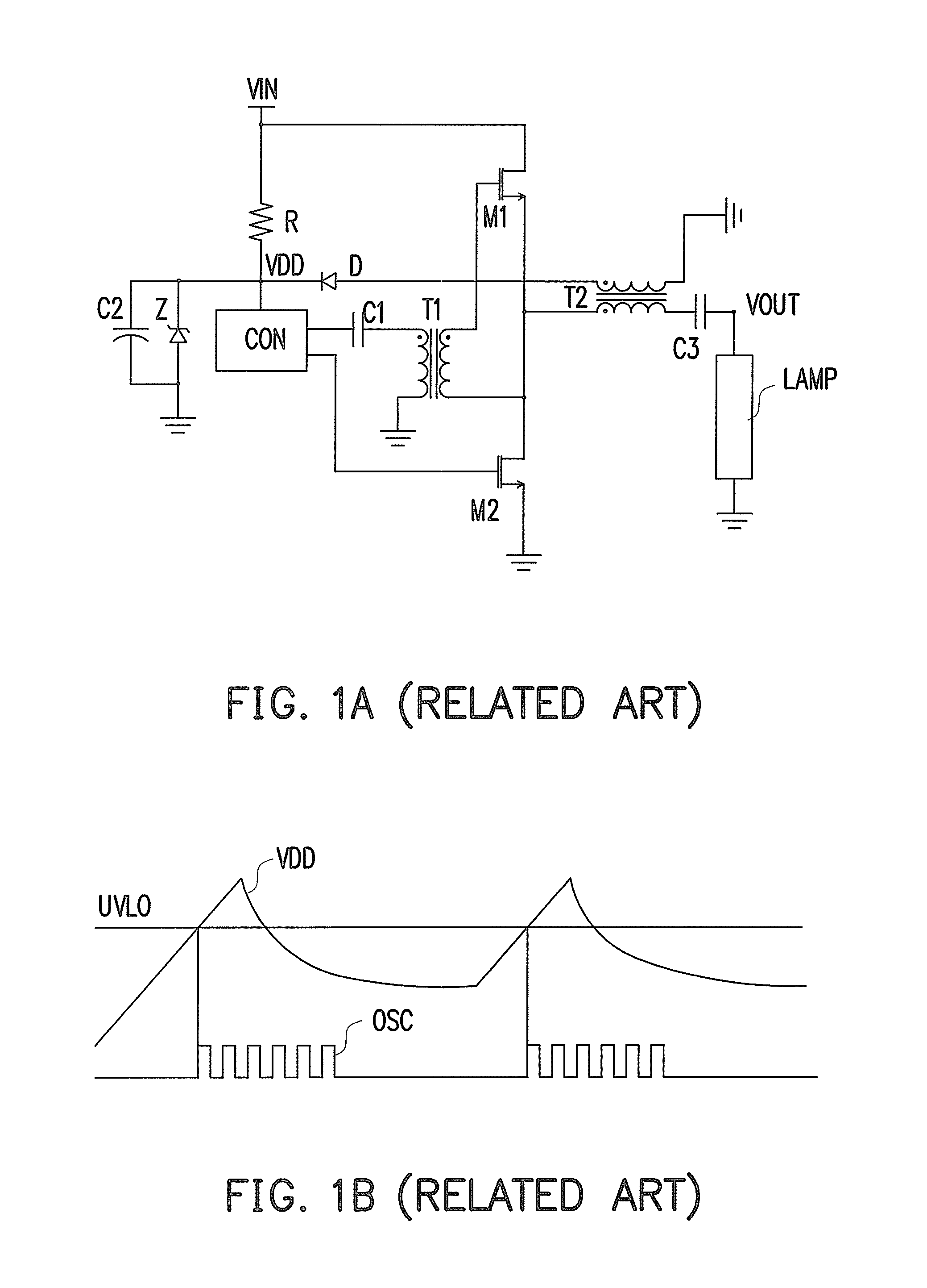
[0032]FIG. 4 is a schematic circuit of a power conversion driving circuit consistent with the invention. Referring to FIG. 4, the power conversion driving circuit includes a control circuit 300, a converting circuit 360, and a load circuit 380. The converting circuit 360 is a flyback voltage converting circuit including a transformer T, a first diode D1, a second diode D2, a switch SW1, and an output capacitor Co. The converting circuit 360 is configured to receive an input voltage VIN and converts the received input voltage VIN up to the output voltage VOUT. The input voltage VIN is generated by rectifying a voltage from an AC voltage source VAC through a bridge rectifier BD and then stabilizing the rectified voltage through an input capacitor Cin. The transformer T has a primary coil L1, a secondary coil L3, and an auxiliary coil L2. One terminal of the primary coil L1 is coupled to the input voltage VIN, and the other terminal of the primary coil L1 is coupled to the switch SW1....

third embodiment

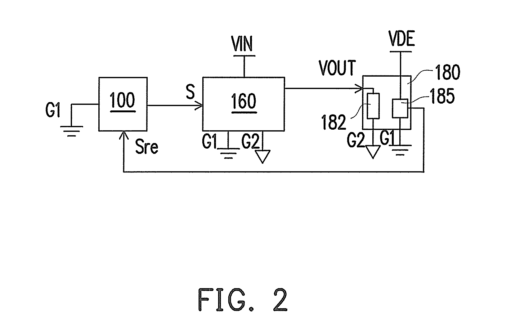
[0037]FIG. 5 is a schematic circuit of a power conversion driving circuit consistent with the invention. Referring to FIG. 5, the power conversion driving circuit includes a control circuit 400, a converting circuit 460, and a load circuit 480. The converting circuit 460 is a full-bridge DC / AC converting circuit. The primary side of the converting circuit 460 is coupled to a first common voltage level G1, and the secondary side thereof is coupled to a second common voltage level G2. The converting circuit 460 is configured to convert a DC input voltage VIN to an AC output voltage VO to drive a fluorescent lamp 482 in the load circuit 480. The load circuit 480 includes the fluorescent lamp 482 and a load detecting unit 485. Two terminals of the fluorescent lamp 482 are respectively coupled to the AC output voltage VO and the second common voltage level G2 through a first connecting terminal c1 and a second connecting terminal c2. Two terminals of the load detecting unit 485 are resp...


PUM


Abstract

A power conversion driving circuit is provided. The power conversion drive circuit includes a converting circuit, a control circuit and a load circuit. The converting circuit is coupled to an input voltage. The control circuit is coupled to the converting circuit for controlling the converting circuit to convert the input voltage to an output voltage. The load circuit includes a load detecting unit and a load. The load is coupled to the output voltage, and the load detecting unit is coupled to a detecting voltage source. The load detecting unit generates a load detecting signal to re-start the control circuit when the load circuit is inserted into the power conversion driving circuit.

Description

CROSS-REFERENCE TO RELATED APPLICATION[0001]This application claims the priority benefit of Taiwan application serial no. 098127316, filed on Aug. 13, 2009. The entirety of the above-mentioned patent application is hereby incorporated by reference herein and made a part of this specification.BACKGROUND OF THE INVENTION[0002]1. Field of the Invention[0003]The invention generally relates to a power conversion driving circuit, and more particularly, to a power conversion driving circuit having the function of automatically turning off and re-starting.[0004]2. Description of Related Art[0005]Current power supplies are mainly classified into linear power supplies (LPS) and switching power supplies (SPS). The LPS has a simple circuit, small ripples, and less electro-magnetic interference (EMI). However, electric devices in the circuit are large, so that the volume of the circuit is large, and the weight thereof is heavy, and further, conversion efficiency thereof is low. On the contrary, ...

Claims


Application Information

Patent Timeline
Patent Type & Authority Patents(United States)
IPC IPC(8): H05B41/16H05B37/00H05B39/00H05B41/24H05B41/36
CPCH05B33/089H05B41/2985H05B47/20H05B47/28H05B45/56H05B45/50
Inventor YU, CHUNG-CHE
Owner GREEN SOLUTION TECH CO LTD
Why Eureka
Try Eureka