Process for the synthetic generation of methane

Active Publication Date: 2012-11-20
PAUL SCHERRER INSTITUT
View PDF11 Cites 0 Cited by
  • Summary
  • Abstract
  • Description
  • Claims
  • Application Information

AI Technical Summary

Benefits of technology

[0010]Accordingly, it is the aim of the invention to provide a process which allows the synthetic generation of methane

Problems solved by technology

Unfortunately, one of the most preferred renewable raw material, wood, cannot be transformed into bio gas by fermentation.
As far as wood is considered as the renewable raw material, it has to be pointed out that the raw synthesis gas originating from the gasification step, is loaded with considerable a

Method used


Image

  • Process for the synthetic generation of methane
  • Process for the synthetic generation of methane
  • Process for the synthetic generation of methane

Examples


Example

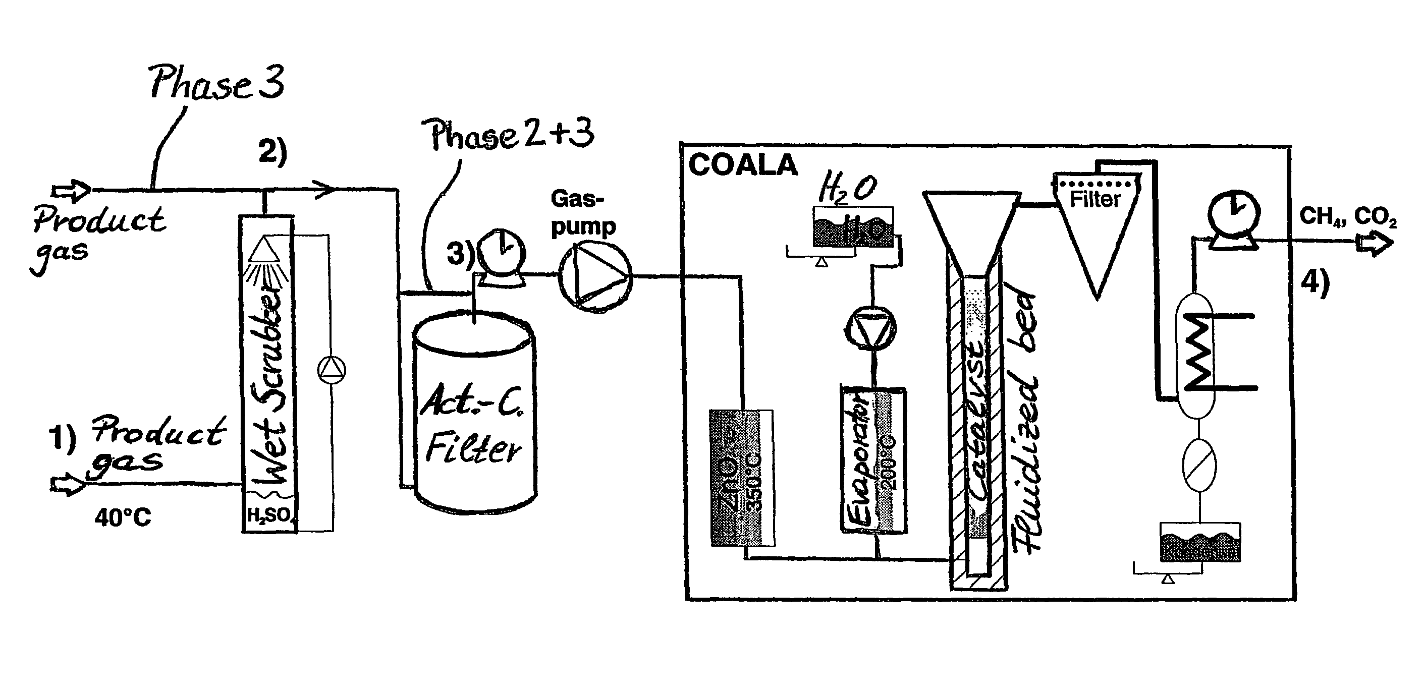
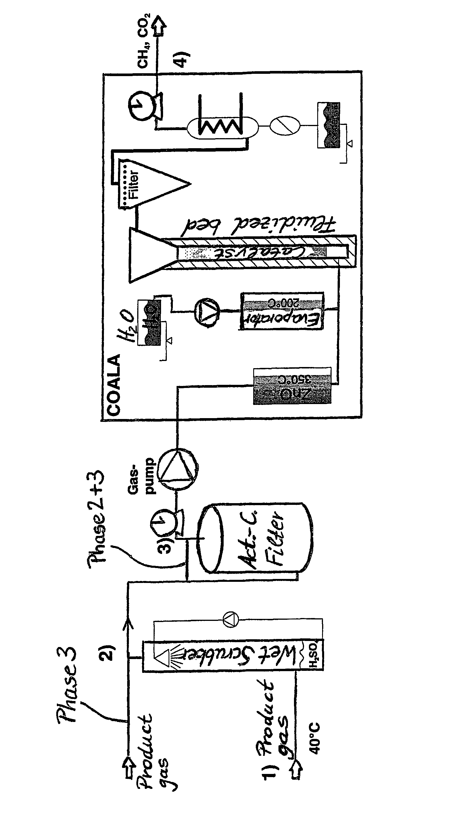
[0023]Exemplarily embodiments of the inventive process are described in detail below without the intention to limit the invention to these actually preferred examples.

[0024]Various measurements have been taken with a plant as shown schematically below in FIG. 1. The measurement campaign can be divided in three different sections:[0025]Phase 1: The feed gas mixture is pretreated with a wet scrubber unit and an activated carbon filter (charcoal absorber) as proposed so far in the prior art which teaches the process as being unactable without prior gas cleaning and removal of aromatic hydrocarbons;[0026]Phase 2: The feed gas mixture is now only pretreated with the wet scrubber unit; charcoal absorber has been bypassed being aware of a possible catalyst deactivation reported so far in the prior art due to carbon which is deposited on the catalytic surfaces and by that blocks their reactivity (coking); and[0027]Phase 3: The feed gas mixture is taken as of the outlet of the wood gasificat...


PUM


Abstract

In a process for the synthetic generation of methane from a feed gas mixture, a feed gas mixture including carbon monoxide, hydrogen, water vapor, CO2, volatile hydrocarbons comprising C2 and higher, unsaturated C2 components and aromatic hydrocarbons in the range of 1 to 10 vol % is provided. The feed gas mixture is contacted with a fluidized bed catalyst having catalyst particles having a catalytic active component selected from the group consisting of a metal, a metal compound and combinations thereof. The contacting occurs at an elevated temperature in the range of 250 to 450° C., a feed gas pressure in the range of 0.8 to 70 bar, a gas hourly space velocity of 1000 to 50000 h−1, and a concentration of H2/CO in the gas mixture in the range of 0.25 to 5.

Description

CROSS REFERENCE TO RELATED APPLICATIONS[0001]This application is the US National Stage of International Application No. PCT / EP2005 / 000637, filed Jan. 24, 2005 and claims the benefit thereof. The International Application claims the benefits of European Application No. EP 04003198.1 filed Feb. 12, 2004, both of the applications are incorporated by reference herein in their entirety.FIELD OF THE INVENTION[0002]The invention relates to a process for the synthetic generation of methane from a feed gas mixture comprising carbon monoxide, hydrogen and water vapour and optionally aromatic hydrocarbons.BACKGROUND OF THE INVENTION[0003]It is the intention of the world-wide community to reduce the production of gaseous climate relevant components, such as chlorofluorocarbons (CFC) and carbon dioxide. For the carbon dioxide the worldwide community committed itself to reduce the production within the next decade in the range of about 10 to 15%, depending on the country and its commitment to the...

Claims


Application Information

Patent Timeline
IPC IPC(8): B23K35/38C07C1/04C07C1/10C07C9/04
CPCC07C1/04C07C1/10C07C1/043C07C1/046C07C2523/755Y02E50/30C07C9/04
Inventor SEEMANN, MARTINBIOLLAZ, SERGESTUCKI, SAMUEL
Owner PAUL SCHERRER INSTITUT
Why Eureka
Try Eureka