Image transmitting apparatus, image receiving apparatus, image transmitting and receiving system, recording medium recording image transmitting program, and recording medium recording image receiving program

a technology which is applied in the field can solve the problems of image quality degradation and data volume reduction, and achieve the effects of reducing the capacity of image transmission and storage, high-quality images, and reducing the data transmission load placed on the network

Active Publication Date: 2012-11-20
SONY CORP
View PDF18 Cites 4 Cited by
  • Summary
  • Abstract
  • Description
  • Claims
  • Application Information

AI Technical Summary

Benefits of technology

[0011]When image capturing is performed with a wide angle of view, the ratio of a region of importance to the entire monitoring image is often small. For example, for monitoring an intruder, it is necessary that only the intruder be displayed or recorded at high resolution. In other words, it is not necessary to check in detail a region or background with little or no change. That is, even when the resolution of an image sensor is improved, a region of less importance (e.g., background region) may be transmitted or recorded at lower resolution, as long as the resolution of a region of importance is maintained. This is advantageous, for example, in that necessary transmission and storage capacities can be reduced.
[0030]According to an embodiment of the present invention, while capacities necessary for image transmission and storage can be reduced, a high-quality image can be restored in a region of importance. That is, while a data transmission load placed on the network can be reduced, resolution in the region of importance can be improved and thus, an accurate monitoring operation can be performed.

Problems solved by technology

In the method in which the amount of data is reduced by increasing the compression ratio in image compression, image quality is degraded since it is difficult to take full advantage of high-resolution image capturing.
However, since the resolution of the image remains the same as the original resolution, the amount of data is not greatly reduced.

Method used


Image

  • Image transmitting apparatus, image receiving apparatus, image transmitting and receiving system, recording medium recording image transmitting program, and recording medium recording image receiving program
  • Image transmitting apparatus, image receiving apparatus, image transmitting and receiving system, recording medium recording image transmitting program, and recording medium recording image receiving program
  • Image transmitting apparatus, image receiving apparatus, image transmitting and receiving system, recording medium recording image transmitting program, and recording medium recording image receiving program

Examples


Embodiment Construction

[0041]Hereinafter, embodiments of the present invention will be described with reference to the drawings.

(Image Transmitting and Receiving System)

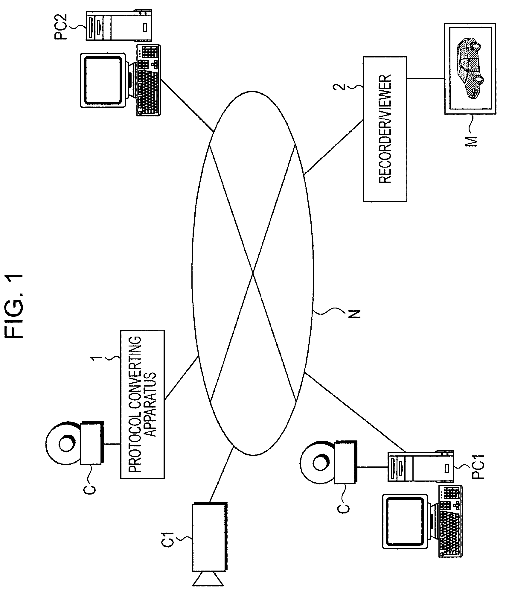
[0042]FIG. 1 illustrates a configuration of an image transmitting and receiving system. The image transmitting and receiving system has a configuration in which image transmitting devices and image receiving devices are connected to one another via a network N. Examples of the transmitting devices include a camera C, a protocol converting apparatus 1, a transmitting camera C1 with a transmitting function, and a transmitting computer PC1 with a transmitting function. Examples of the receiving devices include a recorder / viewer 2 and a receiving computer PC2 with a receiving function.

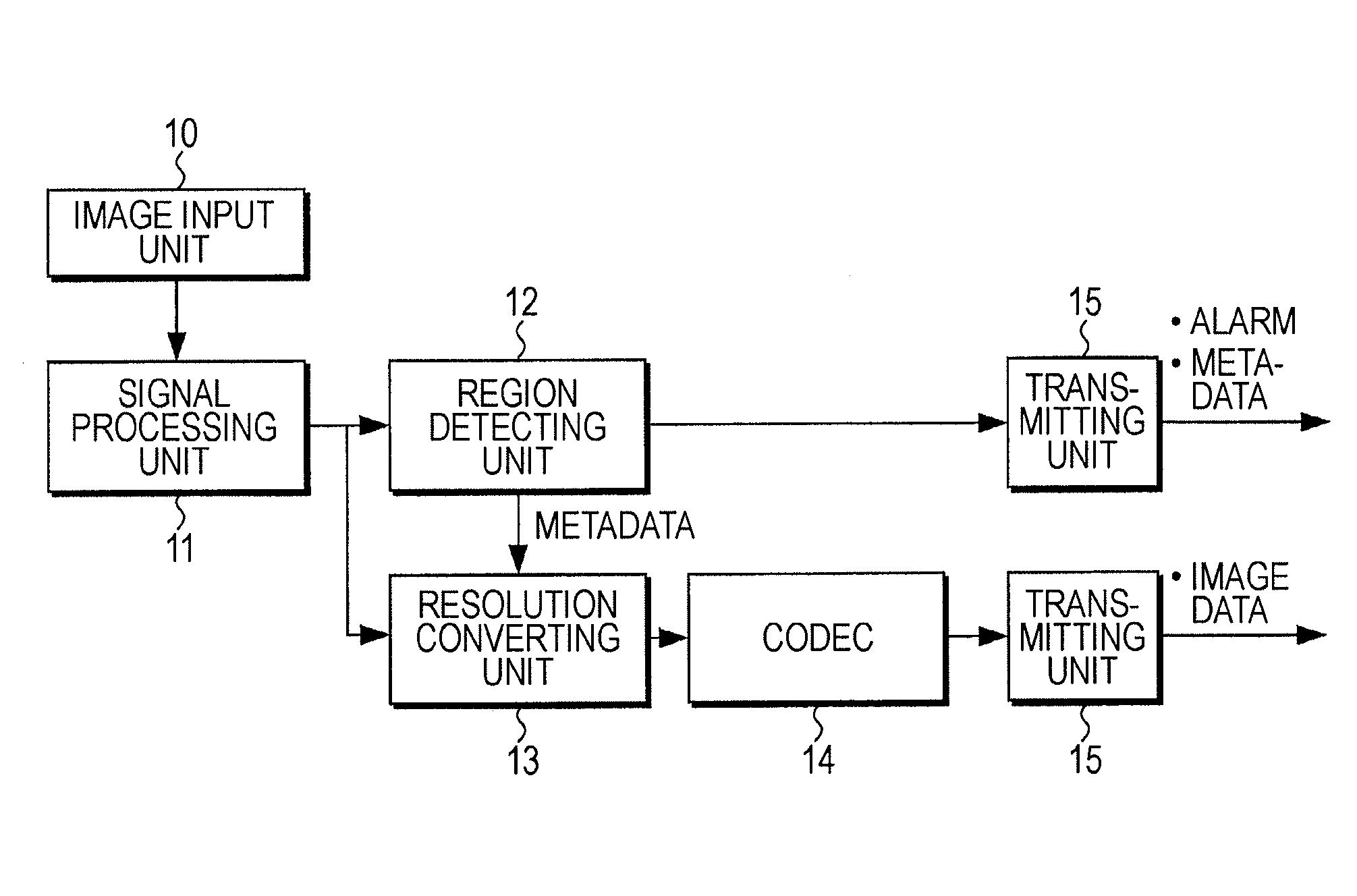
[0043]An image transmitting apparatus of the present embodiment may be included in a transmitting device as a hardware component. Alternatively, an image transmitting program of the present embodiment may be implemented in a transmitting device as a software comp...


PUM


Abstract

An image transmitting apparatus includes a region detecting unit detecting, in an image, a region of interest matching a predetermined condition; a resolution converting unit selecting, for reducing resolution of the image, an image passed through a low-pass filter as an image outside the detected region of interest and an image not passed through the low-pass filter as an image inside the region of interest; and a transmitting unit transmitting the image with reduced resolution and positional information of the region of interest. An image receiving apparatus includes a resolution restoring unit performing image quality improvement processing on the region of interest obtained from the positional information and included in the image transmitted from the image transmitting apparatus so as to increase resolution in the region of interest; and a combining unit combining the image inside the processed region of interest with the image outside the region of interest.

Description

CROSS REFERENCES TO RELATED APPLICATIONS[0001]The present invention contains subject matter related to Japanese Patent Application JP 2008-027366 filed in the Japanese Patent Office on Feb. 7, 2008, the entire contents of which are incorporated herein by reference.BACKGROUND OF THE INVENTION[0002]1. Field of the Invention[0003]The present invention relates to an image transmitting apparatus capable of dividing an image into a region of interest and a region of non-interest, applying different types of processing to images in the respective regions, and transmitting the processed images; an image receiving apparatus capable of receiving and combining together the images in the region of interest and region of non-interest transmitted from the image transmitting apparatus; an image transmitting and receiving system including the image transmitting apparatus and the image receiving apparatus; an image transmitting program; and an image receiving program.[0004]2. Description of the Rela...

Claims


Application Information

Patent Timeline
Patent Type & Authority Patents(United States)
IPC IPC(8): G06K9/32G06T1/00G06T3/40G06T5/00G06T5/20H04N1/387H04N1/393H04N7/173H04N7/18H04N21/2187H04N21/2662
CPCG06T3/4092H04N19/117H04N19/85H04N19/17H04N19/20H04N19/136
Inventor HAYASHI, KAZUYOSHI
Owner SONY CORP
Why Eureka
Try Eureka