

Endoluminal stent having mid-strut interconnecting members
a technology of endoluminal stents and interconnected members, which is applied in the field of endoluminal stents, covered stents and stentgrafts, can solve the problems of unimagined unibody stent structural element geometry, compromise longitudinal flexibility and/or hoop strength, etc., and achieves optimal stent elasticity, desirable column strength, and minimize longitudinal flexibility
- Summary
- Abstract
- Description
- Claims
- Application Information
AI Technical Summary
Benefits of technology
Problems solved by technology
Method used
Image

Examples
Embodiment Construction
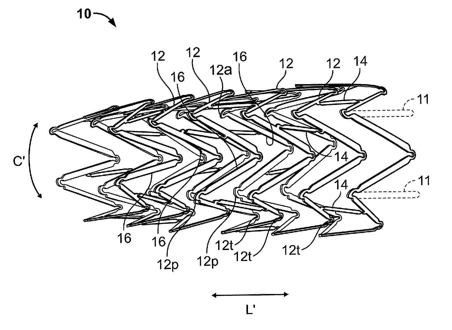
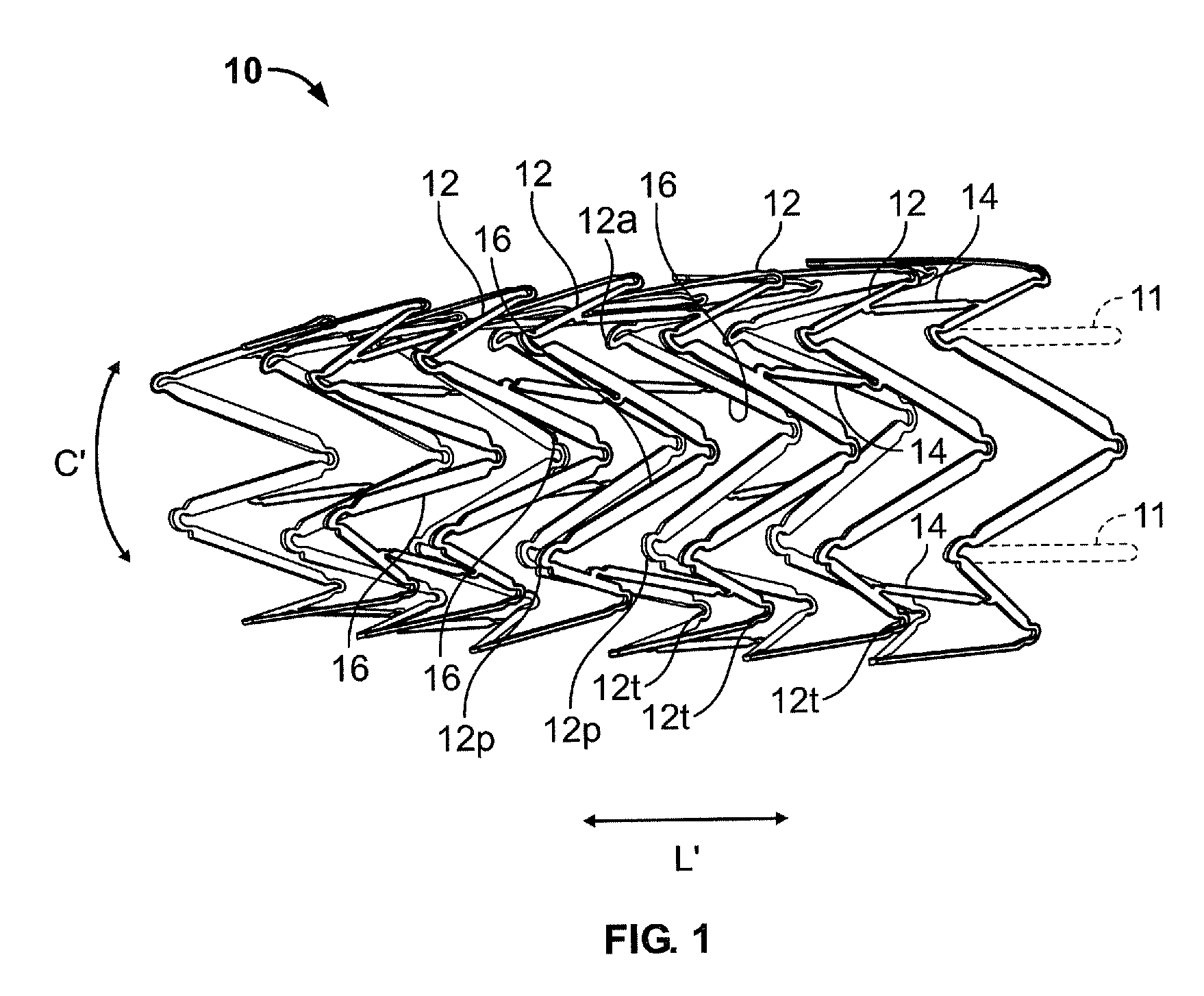
[0023] In accordance with the present invention there is provided several preferred embodiments. In each of the preferred embodiments of the present invention, the general configuration of the inventive endoluminal stent is substantially the same. Specifically and with particular reference to FIG. 1, the inventive endoluminal stent 10 consists generally of a tubular cylindrical element comprised of a plurality of circumferential expansion elements 12 generally forming closed rings about the circumferential axis C′ of the stent 10 and arrayed in spaced apart relationship relative to one another coaxially along the longitudinal axis L′ of stent 10. A plurality of interconnecting members 14 interconnects adjacent pairs of the plurality of circumferential expansion elements 12. Each of the plurality of circumferential expansion elements 12 have a generally sinusoidal configuration with a plurality of peaks 12p and a plurality of troughs 12t of each circumferential expansion member and a...
PUM
| Property | Measurement | Unit |
|---|---|---|
| length | aaaaa | aaaaa |
| outer diameter | aaaaa | aaaaa |
| outer diameter | aaaaa | aaaaa |
Abstract
Description
Claims
Application Information