Arcing fault and arc flash protection system having a high-speed switch

a protection system and high-speed switch technology, applied in the direction of air-break switches, high-tension/heavy-dress switches, switchgear arrangements, etc., can solve the problems of severe injuries to operating personnel, damage to switchgear equipment, and possible dangers of switchgear enclosures

Active Publication Date: 2012-11-27
SCHNEIDER ELECTRIC USA INC
View PDF21 Cites 32 Cited by
  • Summary
  • Abstract
  • Description
  • Claims
  • Application Information

AI Technical Summary

Benefits of technology

[0010]In one embodiment, a high-speed arc terminator for an electrical power distribution system includes a sealed, evacuated housing, and a controllable mechanical switch having first and second electrically conductive contacts enclosed within the housing and adapted to be coupled to the power distribution system outside the housing. At least one of the contacts is movable between an open position in which the contacts are separated by a vacuum gap, and a closed position in which the contacts engage each other, and an operating mechanism is provided for moving the at least one movable contact between the open and closed positions. An arcing fault detector produces a control signal in response to the detection of an arcing fault, and the operating mechanism is responsive to the control signal for moving the at least one movable contact to the closed position. A trigger conductor extends into the housing and has an exposed end near the cathodic contact when the contacts are in the open position. A high-voltage source is controllably coupled to the trigger conductor for supplying a high-voltage pulse to the trigger conductor in response to the detection of an arcing fault. The high-voltage pulse produces an arc between the trigger conductor and the cathodic contact, which helps to establish a secondary arc within the gap between the contacts, to shunt fault current from the arcing fault in the main electrical circuit, through the gap, from one of the contacts to the other, before the contacts engage each other. The shunting of the fault current by the secondary arc, produced with assistance from the trigger conductor, suppresses the arc produced by the arcing fault, limiting the generation of gases at high pressures and / or temperatures, thereby protecting the switchgear equipment from damage and personnel from harm.

Problems solved by technology

In addition to current overloads, the switchgear enclosures may also encounter hazardous conditions known as primary arcing faults Primary arcing faults are typically caused by corroded, worn or aged wiring, loose connections, overloading, lightning strikes, etc.
Especially in medium or high-voltage power distribution systems, the ionized gas associated with primary arcing faults may be released at pressures and temperatures sufficient to severely damage or destroy the switchgear equipment and / or cause severe injuries to operating personnel.
In addition to the ionized gases, there is a large release of incident light energy (lumens) which could be detrimental to personnel.
One problem with arc terminators of the type identified above is that the operating time can be relatively slow, e.g., about 5 milliseconds.
During that time, potential damage to the equipment and personnel can occur.
This device develops an arc in gas, which limits its lifespan, especially for high-voltage applications, by the progressive loss of insulation properties.
Although the operating time of the “arcing crowbar” device described immediately above is relatively faster than the operating time of a completely mechanical crowbar device arc terminator, one problem associated with this “arcing crowbar” device is that it fails to include a redundant system as a back-up.
Another problem with this ablative type of “arcing crowbar” device is that it has a limited lifespan, wherein material essential for operation of the device is lost each time the gun fires.
Furthermore, as essential material is lost, the impedance of the arc diverting path may increase over time, with the number of operations.
Consequently, the likelihood increases that the path of lowest impedance may shift back to the primary arcing fault which, essentially, could cause the “arcing crowbar” device to fail.

Method used


Image

  • Arcing fault and arc flash protection system having a high-speed switch
  • Arcing fault and arc flash protection system having a high-speed switch
  • Arcing fault and arc flash protection system having a high-speed switch

Examples


Embodiment Construction

[0024]Although the invention will be described in connection with certain preferred embodiments, it will be understood that the invention is not limited to those particular embodiments. On the contrary, the invention is intended to include all alternatives, modifications and equivalent arrangements as may be included within the spirit and scope of the invention as defined by the appended claims.

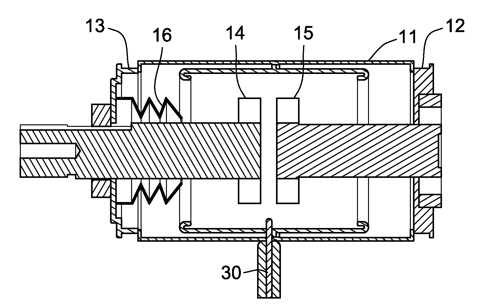
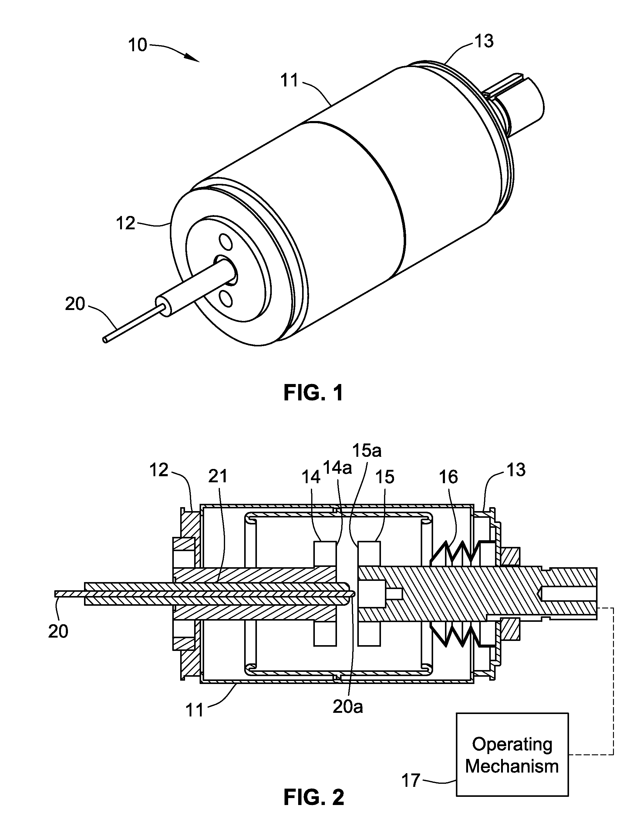
[0025]Referring to FIG. 1, a vacuum bottle for an electrical distribution system has a sealed, evacuated housing 10 for enclosing internal components, including a mechanical switch that can be automatically closed in response to the detection of an arcing fault, to divert fault current to a low impedance path and thus extinguish the arc. The housing 10 includes a body 11 that is typically made of an insulating ceramic material hermetically sealed to a pair of end caps 12 and 13. The sealed cylindrical housing 10, sometimes referred to in the industry as a “vacuum bottle,” is evacuated to crea...


PUM


Abstract

A high-speed arc terminator for an electrical power distribution system includes a sealed, evacuated housing, and a controllable mechanical switch having first and second electrically conductive contacts enclosed within the housing and adapted to be coupled to the power distribution system outside the housing. A trigger conductor extends into the housing and has an exposed end near the gap between the contacts when the contacts are in the open position. At least one of the contacts is movable between an open position in which the contacts are separated by a gap, and a closed position in which the contacts engage each other, and an operating mechanism is provided for moving the at least one contact between the open and closed positions. A high voltage source is controllably coupled to the trigger conductor for supplying a high-voltage pulse to the trigger conductor in response to the detection of an arcing fault. The high-voltage pulse produces an arc within the gap between the contacts, to shunt fault current from the power distribution system across the gap, from one of the contacts to the other, before the contacts engage each other.

Description

FIELD OF THE INVENTION[0001]This invention is directed generally to protective devices for electrical switch gear and, more particularly, to an arcing fault protection system having a high-speed switch for diverting an arc.BACKGROUND OF THE INVENTION[0002]Switchgear enclosures are commonly employed in electrical power distribution systems for enclosing circuit breakers and switching equipment associated with the distribution system. The circuit breakers are used to interrupt electric power in response to hazardous current overloads in a protected circuit.[0003]In addition to current overloads, the switchgear enclosures may also encounter hazardous conditions known as primary arcing faults Primary arcing faults are typically caused by corroded, worn or aged wiring, loose connections, overloading, lightning strikes, etc. Especially in medium or high-voltage power distribution systems, the ionized gas associated with primary arcing faults may be released at pressures and temperatures s...

Claims


Application Information

Patent Timeline
Patent Type & Authority Patents(United States)
IPC IPC(8): H01H33/66
CPCH01H33/66H01H79/00H02B13/065
Inventor BYRON, ELDRIDGE R.SCOTT, GARY W.RODRIGUES, CARLTONRAMSEY, JIMPICOT, PHILIPPE
Owner SCHNEIDER ELECTRIC USA INC
Why Eureka
Try Eureka