Straight tube LED lamp having buckle connecting device for securing all parts together as one body

a technology of connecting device and led lamp body, which is applied in the direction of discharge tube main electrodes, semiconductor devices for light sources, light and heating apparatus, etc., can solve the problems of generating nasty smell, product assembly needs longer time, and substantially shortening service life, so as to prolong the service life of the tube body and save time , the effect of simple assembly

Inactive Publication Date: 2012-11-27
ZHEJIANG SETEC LIGHTING
View PDF11 Cites 44 Cited by
  • Summary
  • Abstract
  • Description
  • Claims
  • Application Information

AI Technical Summary

Benefits of technology

[0010]The invention provides a time-saving LED straight tube type lamp with reasonable design, convenient assembly and long service life, which mainly solves the problems of short service life and poisoning of operators caused by the connection of a lamp cover and a lamp tube by using chemical adhesives and environment pollution.
[0011]The invention aims at solving the problems of unreasonable structure of a lamp strip of the lamp, poor heat diffusion effect and easy occurrence of short circuit in the prior art, and provides an LED straight tube type lamp with reasonable structure, good heat diffusion effect and safe and reliable use.

Problems solved by technology

The adhesives fix the lamp cover on the tube body so that the structure is simple, but the solidification or drying of the adhesives needs certain time, and therefore the product assembly needs longer time.
Meanwhile, the adhesives left at gaps between the lamp cover and the tube body are organic chemicals which slowly decompose or dissociate some chemical substances to erode the surface of the tube body of plastic material so as to result in the aging phenomena such as stains, streaks, cracks and the like, so the service life is substantially shortened; furthermore, the chemical adhesives can generate nasty smell, and can harm the operators and generate pollution to the environment during use.
Undoubtedly, the heat diffusion effect is poor.
1. poor heat diffusion effect, as the foresaid patents of the publication numbers (1), (2), (3) are provided with uniform insulating layers / plates in between circuit layers / plates and heat diffusion layers / plates, the insulating layers / plates have large heat resistance and low heat transmission efficiency so as to result in poor heat diffusion effect; especially the patent of the publication number (2) adopts the mode of insulating plate assembly, and the heat diffusion effect is worse as gaps exist between relevant components; similarly, the patent of the publication number (3) is further provided with an insulation layer between the circuit board and the heat diffusion body, the heat diffusion body is integrated on a casing, so that the heat diffusion effect is worse.
2. unreasonable structure, all the foresaid three patents are in assembly structure which certainly has influence on the heat diffusion effect; the heat diffusion layer of the foresaid patent of the publication number (1) is a copper-aluminum double-metal composite layer, it is impossible to make absolute seamless connection after all despite of being made by adopting cold rolling pressing technology; as numerous micro-fine depressions exist on the surfaces of the copper plate and the aluminum plate, and the copper plate and the aluminum plate have straightness difference, a large amount of air must be contained between the connection surfaces of the copper plate and the aluminum plate and gas phase heat resistance exists between both, which directly has a strong impact on the heat diffusion effect of the heat diffusion layer.
3. Poor reliability, the insulating layers / plates of the foresaid three patents indefinitely are provided with insulating layers with the flame resistance and the surfaces of the circuit boards are not provided with insulating welding resisting layers, so that it is possible to generate short circuit and trigger fire alarm.
4. complicated assembly and connection of the circuit layers / board and the LED light emitting dioxide, the foresaid patent of the publication number (1) realizes the electric connection of both through a base plate; and the patent of the publication number (2) realizes the electric connection of both by making the LED light emitting dioxide penetrate out of a through hole of the insulating plate.

Method used


Image

  • Straight tube LED lamp having buckle connecting device for securing all parts together as one body
  • Straight tube LED lamp having buckle connecting device for securing all parts together as one body
  • Straight tube LED lamp having buckle connecting device for securing all parts together as one body

Examples


Embodiment Construction

[0030]The technical schemes of the invention are elaborated through embodiments by combining figures.

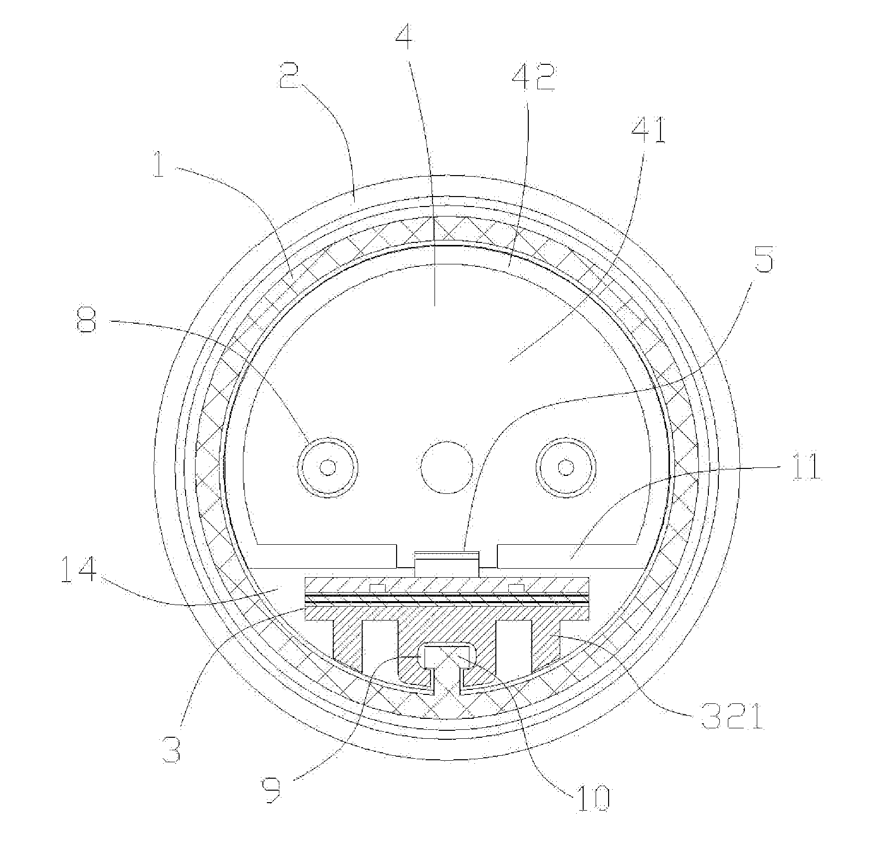
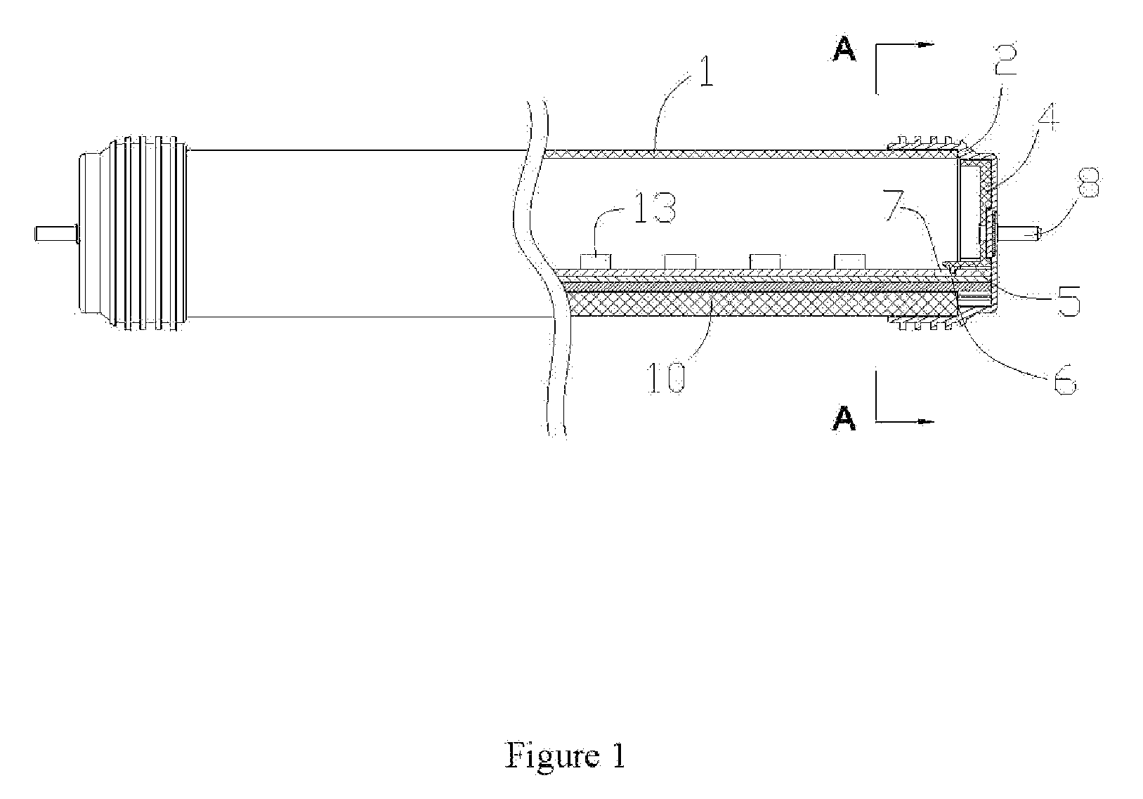
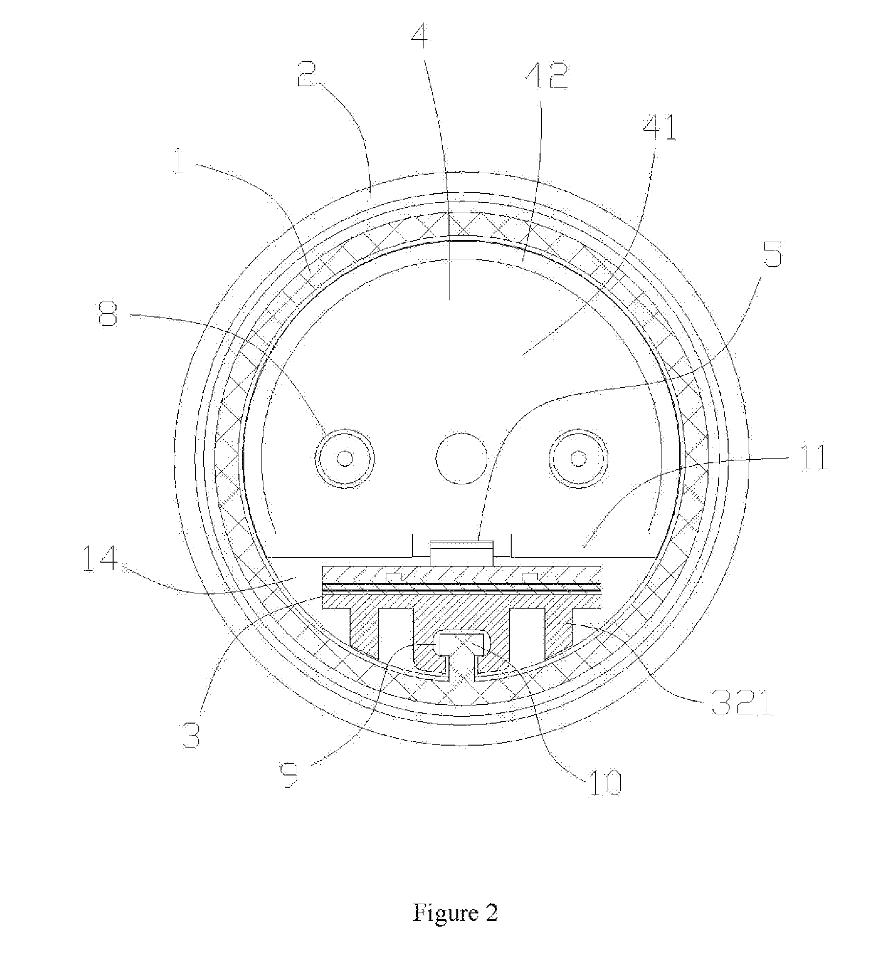
[0031]An LED straight tube lamp of an embodiment as shown in FIGS. 1, 2 comprises a tube body 1 and a lamp strip 3 which is in inserted connection in the tube body; and two ends of the tube body are respectively sheathed with a lamp cover 2 which is fixed on the lamp strip through a connecting device. As shown in FIG. 1, the connecting device comprises a connecting piece 4 which comprises a bottom plate 41 and a short side wall 42 which is arranged along the edge of the bottom plate; the short side wall is C-shaped and attached with the internal wall of the tube body 1; the bottom plate 41 of the connecting piece is in insulated connection with the internal bottom surface of the lamp cover 2 through two lamp pins. The connecting piece is provided with a connecting arm 5 extending along the length direction of the lamp strip; two ends of the short side wall 42 are respectively provide...


PUM


Abstract

A LED lamp with straight tube comprises a tube body, a lamp cover sheathed at two ends of the tube body and a lamp strip which is in inserted connection in the tube body and comprises a circuit board and a heat diffuser; the lamp cover is internally, fixedly provided with a connecting device connected with the lamp strip; the connecting device comprises a connecting piece on which a connecting arm extending along the length direction of the lamp strip is arranged; the connecting arm is provided with a buckle body; the corresponding position on the surface of the lamp strip is provided with a buckle seat matched with the buckle body; and the circuit board is overlapped and adhered with the radiator to be into a whole through an insulating heat conducting layer.

Description

CROSS REFERENCE TO RELATED PATENT APPLICATION[0001]The present application is the US national stage of PCT / CN2009 / 001383 filed on Dec. 7, 2009, which claims the priority of the Chinese patent application No. 200920119576.4 filed on May 10, 2009, which application is incorporated herein by reference.FIELD OF THE INVENTION[0002]The invention relates to an LED lamp, in particular to an LED straight tube type lamp.BACKGROUND OF THE INVENTION[0003]The prior LED straight tube type lamp mainly comprises a tube body, a lamp cover arranged on two ends of the tube body and a lamp strip which is arranged in the tube body, wherein the lamp cover and the tube body are adhered generally by adopting chemical adhesives. The adhesives fix the lamp cover on the tube body so that the structure is simple, but the solidification or drying of the adhesives needs certain time, and therefore the product assembly needs longer time. Meanwhile, the adhesives left at gaps between the lamp cover and the tube bo...

Claims


Application Information

Patent Timeline
Patent Type & Authority Patents(United States)
IPC IPC(8): H01J7/24
CPCF21K9/17F21S4/008F21Y2103/003F21Y2101/02F21S4/28F21Y2103/10F21Y2115/10F21K9/275
Inventor KE, JIANFENG
Owner ZHEJIANG SETEC LIGHTING
Why Eureka
Try Eureka