Lines-of-sight and viewsheds determination system

a technology of viewsheds and determination systems, applied in the field of linesofsight and viewsheds determination systems, can solve the problems of old methods limited to a stationary sniper, target, or observer, and achieve the effect of reducing transparency

Active Publication Date: 2012-12-04
THE UNITED STATES OF AMERICA AS REPRESENTED BY THE SECRETARY OF THE NAVY
View PDF16 Cites 80 Cited by
  • Summary
  • Abstract
  • Description
  • Claims
  • Application Information

AI Technical Summary

Benefits of technology

[0016]Old methods cannot determine optimal firing or viewing positions based on constrained angles between the viewer and targets. The invention shows firing po

Problems solved by technology

Old methods are limited to a stati

Method used


Image

  • Lines-of-sight and viewsheds determination system
  • Lines-of-sight and viewsheds determination system
  • Lines-of-sight and viewsheds determination system

Examples


Embodiment Construction

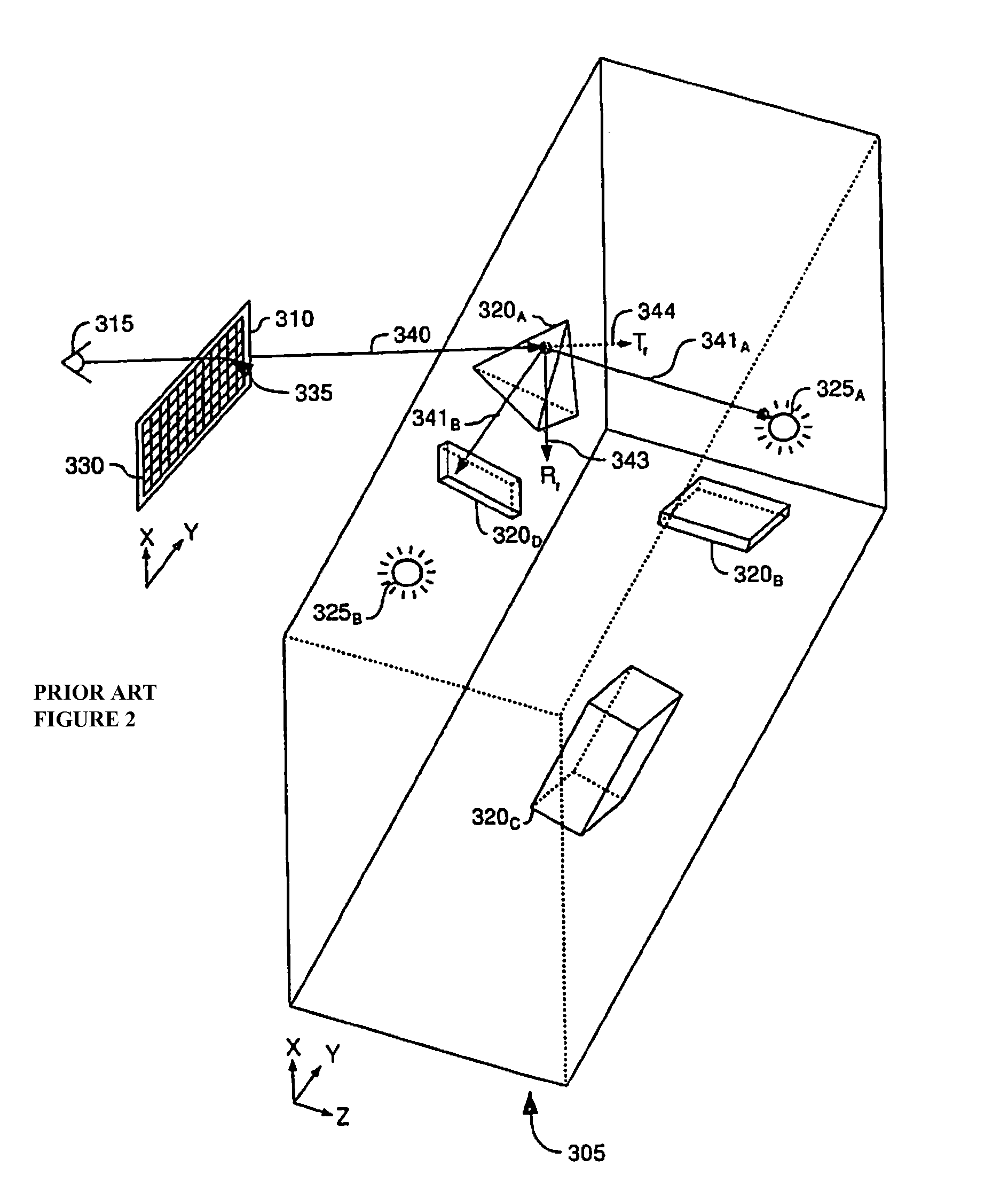
[0037]The present invention employs ray tracing, e.g. as described in U.S. Pat. No. 4,865,423, by Akio Doi, issued Sep. 12, 1989, and in Turner Whined, “An Improved Illumination Model for Shaded Display”, Communications of the ACM, Vol. 23, No. 6, pp. 343-49 (June 1980), both of which are incorporated herein by reference. Ray tracing is also described in Rob Cook and Ken Torrance, “A Reflectance Model for Computer Graphics”, ACM Transactions on Graphics, Vol. 1, No. 1 (January 1982), also incorporated herein by reference.

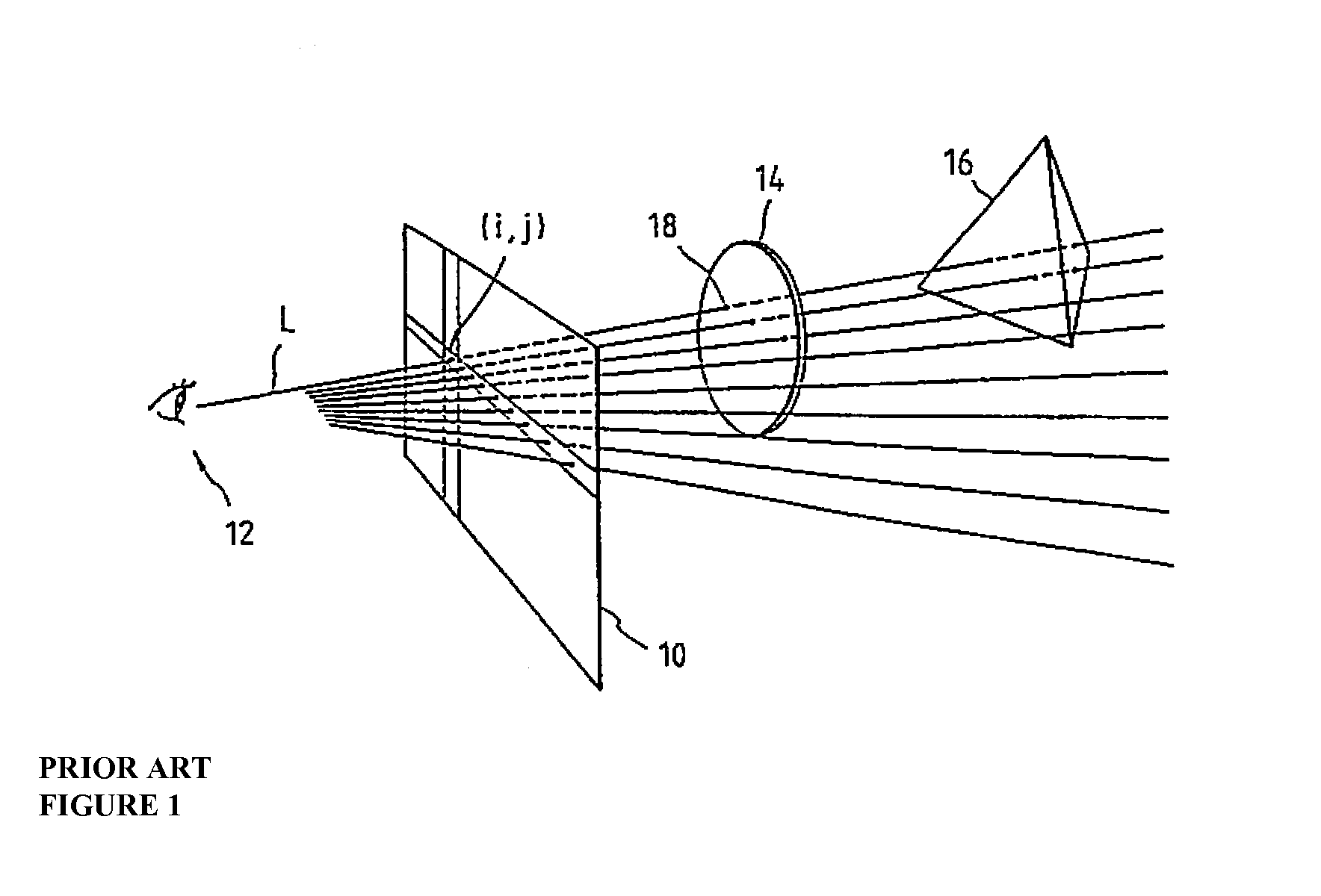
[0038]Ray tracing, shown in FIG. 1, starts with a ray L (Line of Sight, or “LOS”), emitted from a viewpoint 12, that is posited for each pixel (I,j) on screen 10 (matched with a plane of projection), and the surfaces of objects intersecting ray L are searched. Of objects 14 and 16, the first intersected by ray L and the first seen is object 14 whose intersecting surface is closer to the viewpoint.

[0039]Another description of ray tracing is found in US Patent Applica...


PUM


Abstract

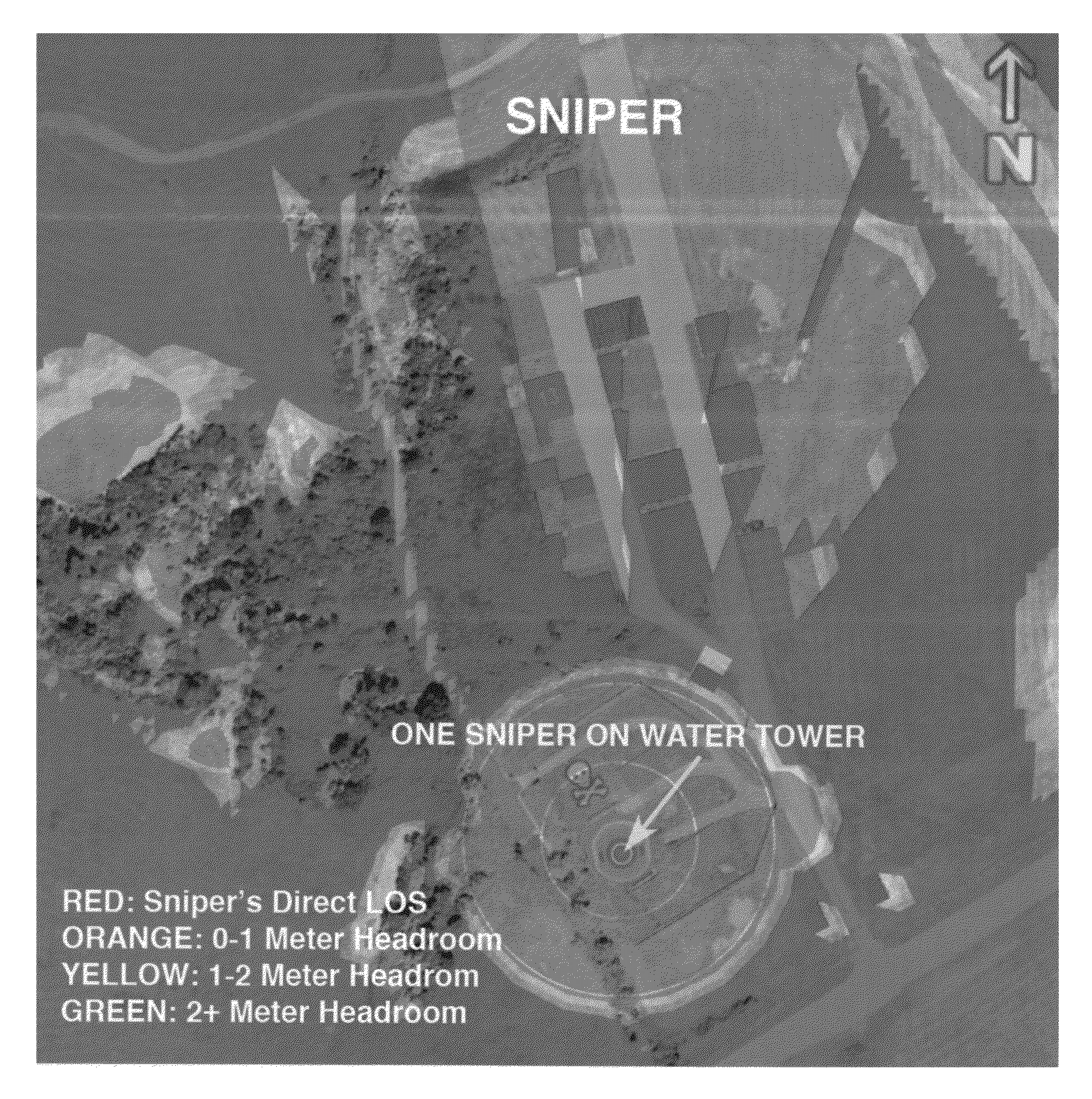
A method for processing three-dimensional data that defines a three-dimensional scene, and determining and displaying lines-of-sight (LOS) and viewsheds on all visible surfaces of the scene, includes: i) assigning at a user-selected location at least one viewpoint in the scene; ii) applying ray tracing from locations in the scene to the viewpoint to determine locations in the scene that are in a line of sight (LOS) and outside the LOS of the viewpoint, thus determining the viewshed relative to the viewpoint; and iii) color-coding every visible surface in the scene. The color coding then differentially indicates the locations in the line of sight (LOS) and outside the LOS of the viewpoint, producing a display of a color-coded viewshed relative to the viewpoint. Additionally ray tracing can be applied from locations above the scene to determine headroom contours for those locations in the scene.

Description

CROSS-REFERENCE TO RELATED APPLICATIONS[0001]This application is a Non-Prov of Prov (35 USC 119(e)) application 60 / 992,343 filed on Dec. 5, 2007.BACKGROUND OF THE INVENTION[0002]The present invention relates generally to a method and software for indicating areas visible to snipers, sentries, or any observers at known positions, as well as for indicating positions from which these entities can be seen. In particular, the present invention uses digital 3D terrain data that is obtained from stereo imagery, LIDAR, or any source of elevation data to determine and display such locations.[0003]Previous methods for determining lines-of-sight (LOS) and viewsheds have various disadvantages. For example, such approaches are limited to one sniper or viewpoint. In a combat environment there are often many snipers, look-outs, and adversaries whose viewsheds must be known. Prior systems are also limited to a stationary sniper, target, or observer. In reality, targets and snipers change positions ...

Claims


Application Information

Patent Timeline
IPC IPC(8): G06T15/00
CPCG06T15/06G06T17/05
Inventor DOYLE, JR., ROBERT J
Owner THE UNITED STATES OF AMERICA AS REPRESENTED BY THE SECRETARY OF THE NAVY
Why Eureka
Try Eureka