Walking robot

a robot and walking technology, applied in the field of walking robots, can solve the problems of complex control mechanism in order to effectively alleviate impact, apply large load to the actuator for operating the hip joint, etc., and achieve the effects of enhancing the driving structure of the pitch-direction hip joint and the knee joint, reducing power consumption, and simplifying the control mechanism

Active Publication Date: 2012-12-11
SAMSUNG ELECTRONICS CO LTD
View PDF11 Cites 5 Cited by
  • Summary
  • Abstract
  • Description
  • Claims
  • Application Information

AI Technical Summary

Benefits of technology

[0012]Therefore, one aspect of embodiments of the present invention is to provide a walking robot, in which driving structures of pitch direction hip joints and knee joints are enhanced so that a control mechanism is simplified and an inertial force generated from legs while walking is reduced to allow the robot to walk more naturally with a smaller power output.
[0033]In accordance with another aspect, embodiments of the present invention provide a robot including a planetary gear unit selectively transmitting driving power inputted into a first input shafts and a second input shaft into an output shaft, and a speed reducer including a third input shaft geared with the output shaft, wherein the planetary gear unit, and speed reducer cooperate to reduce an inertial force generated from legs of the robot while the robot is walking.

Problems solved by technology

However, since the respective joints of the conventional walking robot, particularly the pitch direction hip joints and the knee joints, are independently operated by respective actuators having different capabilities, the control mechanism for such is complicated in order to effectively alleviate the impact.
Further, since the actuator for operating the knee joint is disposed adjacent to the knee joint, a large inertial force is generated from the leg while walking and thus applies a large load to the actuator for operating the hip joint.

Method used


Image

  • Walking robot
  • Walking robot
  • Walking robot

Examples


Embodiment Construction

[0045]Reference will now be made in detail to the embodiments, examples of which are illustrated in the accompanying drawings, wherein like reference numerals refer to the like elements throughout. The embodiments are described below to explain the present invention by referring to the figures.

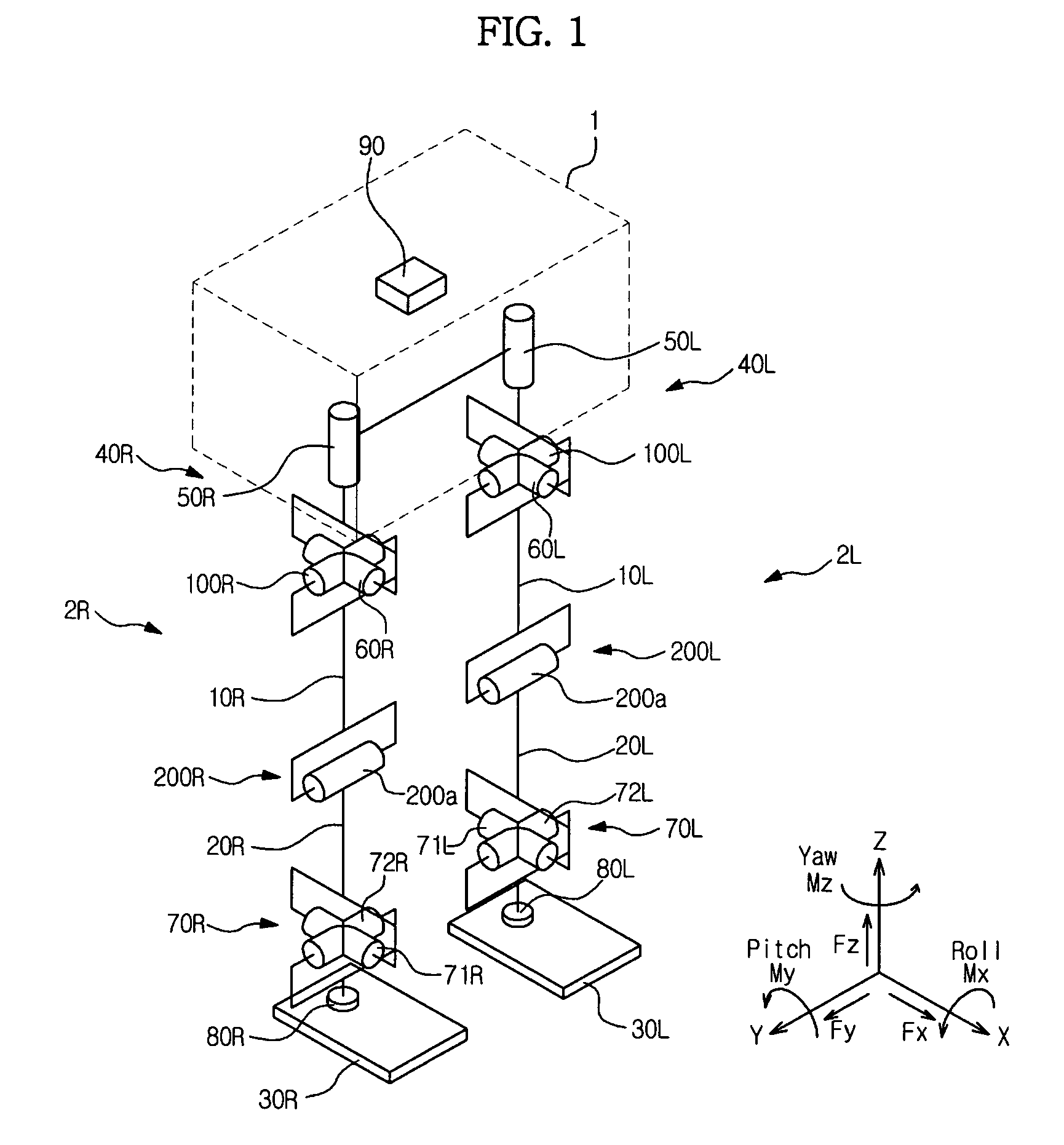
[0046]FIG. 1 illustrates a schematic perspective view of structures of joint units of legs of a walking robot in accordance with an embodiment of the present invention.

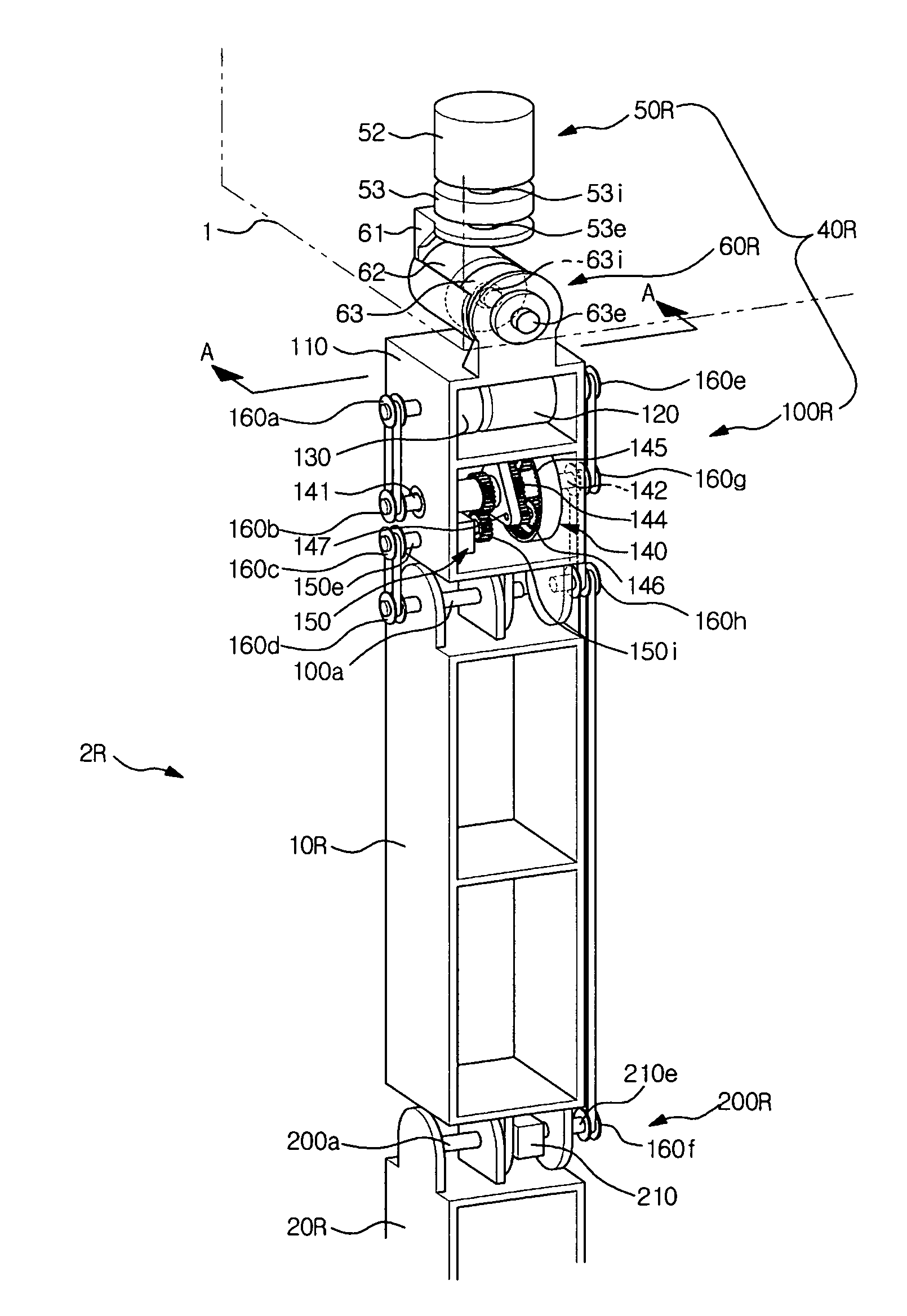
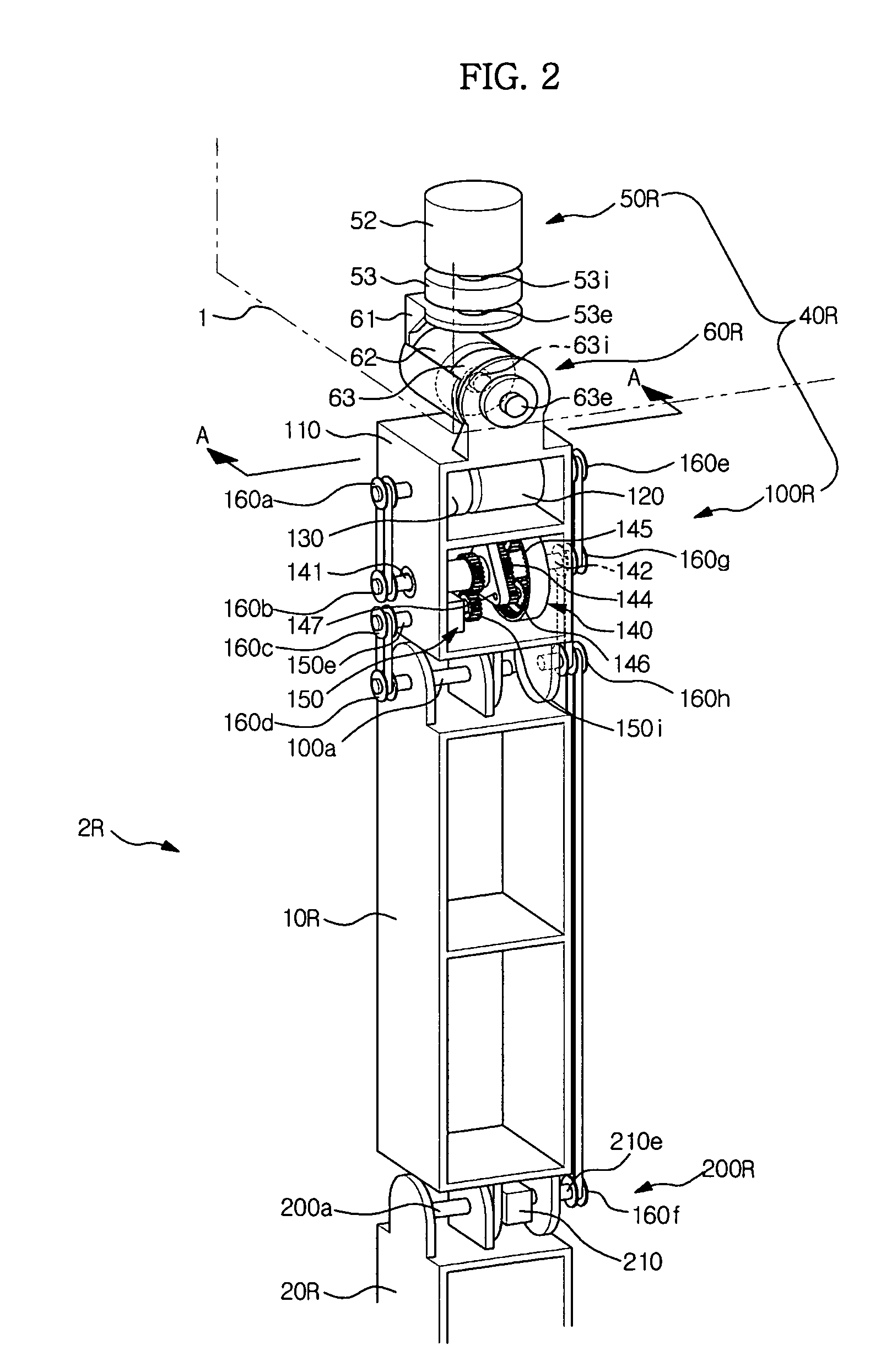
[0047]As shown in FIG. 1, a robot of embodiments of the present invention includes legs 2L and 2R connected to both sides of the lower portion of a trunk 1. Here, L represents the left side, and R represents the right side.

[0048]Links, such as arms, a head, etc., are attached to the trunk 1, or separate devices, such as an input device, a display device, etc., are provided at the trunk 1.

[0049]The legs 2L and 2R respectively include thigh links 10L and 10R, calf links 20L and 20R provided at the lower portions of the thigh links...


PUM


Abstract

A walking robot, in which driving structures of a pitch direction hip joint and a knee joint of a leg are enhanced. The walking robot includes a trunk, and a plurality of legs connected to the trunk, at least one leg among the plurality of legs includes a thigh link, a calf link provided at the lower portion of the thigh link, a pitch direction hip joint connecting the trunk and the thigh link and rotating the thigh link against the trunk in a pitch direction, and a knee joint connecting the thigh link and the calf link and rotating the calf link against the thigh link in the pitch direction. The pitch direction hip joint and the knee joint are interlocked with each other and are driven by one interlocking actuator.

Description

CROSS-REFERENCE TO RELATED APPLICATION[0001]This application claims the benefit of Korean Patent Application No. 2008-0050847, filed May 30, 2008, in the Korean Intellectual Property Office, the disclosure of which is incorporated herein by reference.BACKGROUND[0002]1. Field[0003]Embodiments of the present invention relate to a walking robot, and more particularly to a walking robot, in which driving structures of a pitch direction hip joint and a knee joint of a leg are enhanced.[0004]2. Description of the Related Art[0005]In general, walking robots having various shapes, such as biped and quadruped shapes, have been developed for household, military, and industrial purposes.[0006]Korean Patent Laid-open Publication No. 2001-0050273 discloses a humanoid, i.e., a biped walking robot.[0007]The humanoid disclosed in Korean Patent Laid-open Publication No. 2001-0050273 includes a trunk, a head provided at the upper end of the trunk, a pair of arms provided at both sides of the upper po...

Claims


Application Information

Patent Timeline
Patent Type & Authority Patents(United States)
IPC IPC(8): B62D57/02
CPCA63H11/00B62D57/032A63H2200/00A63H11/18B25J17/0258B25J9/102Y10S901/01
Inventor LEE, YOUN BAEKOH, YEON TAEKYANG, SOO SANG
Owner SAMSUNG ELECTRONICS CO LTD
Why Eureka
Try Eureka