
Method and system for generating sulfur seeds and granules

a technology of which is applied in the field of method and system for generating sulfur seeds and granules, can solve the problems of unfavorable environmental protection, explosion and/or health hazards, and the formation of dust, etc., to achieve the effect of reducing the exposure to enlarging sulfur spray, reducing the risk of explosion, and increasing or reducing the production of granules

Active Publication Date: 2012-12-11
IPCO US LLC
View PDF114 Cites 5 Cited by
  • Summary
  • Abstract
  • Description
  • Claims
  • Application Information

AI Technical Summary

Benefits of technology

"The patent describes a process for producing sulfur seeds by spraying liquid molten sulfur onto a cooling liquid in a tank. The solidified sulfur seeds are then formed and can be further enlarged into sulfur granules. The process allows for dynamic changes to flow rates, temperatures, and pressures to increase or decrease granule production without shutting down the system. The granulating drum used in the process has lifting flights that help move the sulfur bed to the discharge end faster. The lifting flights are attached with rib members to minimize the exposure of larger sulfur seeds to the enlarging sulfur spray. The technical effects of the patent include improved production efficiency, flexibility, and reduced downtime for maintenance."

Problems solved by technology

A disadvantage with crushing is that dust is created that may become released into the environment.
The dust may be explosive and / or a health hazard.
Also, the crushings are not uniform in size or spherical in shape.
However, the fans may become unbalanced from the sulfur that accumulates on the blades.
A disadvantage of producing seeds in a granule enlargement drum is that the conditions required in the drum for optimum granule production are not the same conditions required for optimum seed production.

Method used


Image

  • Method and system for generating sulfur seeds and granules
  • Method and system for generating sulfur seeds and granules
  • Method and system for generating sulfur seeds and granules

Examples


Embodiment Construction

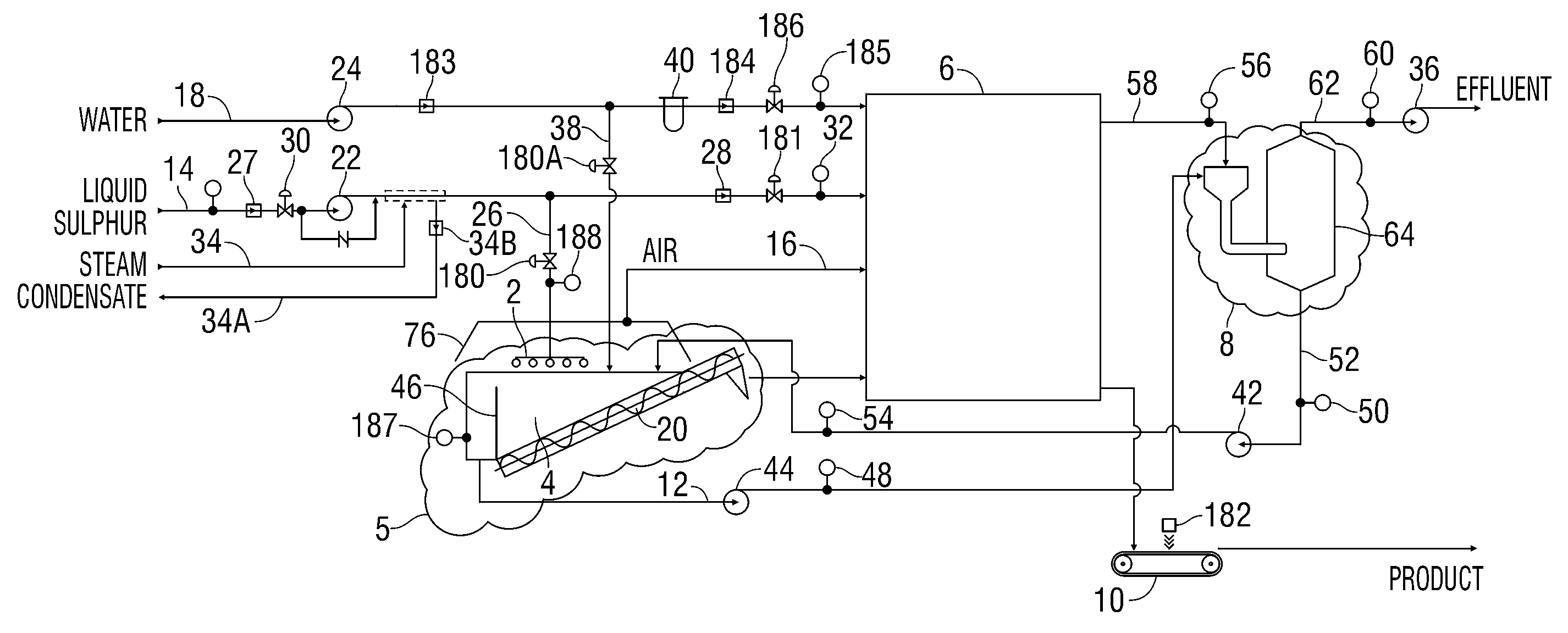
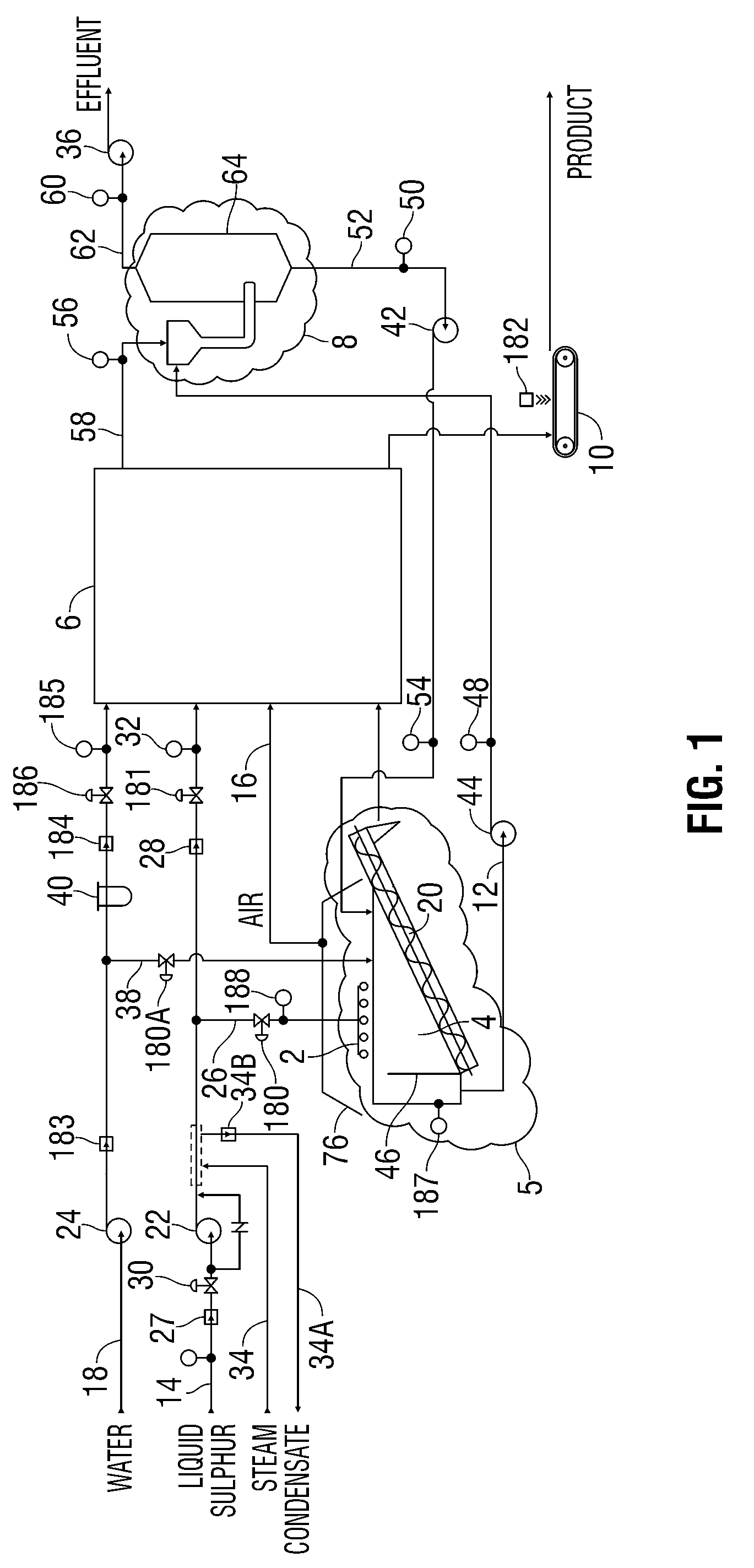
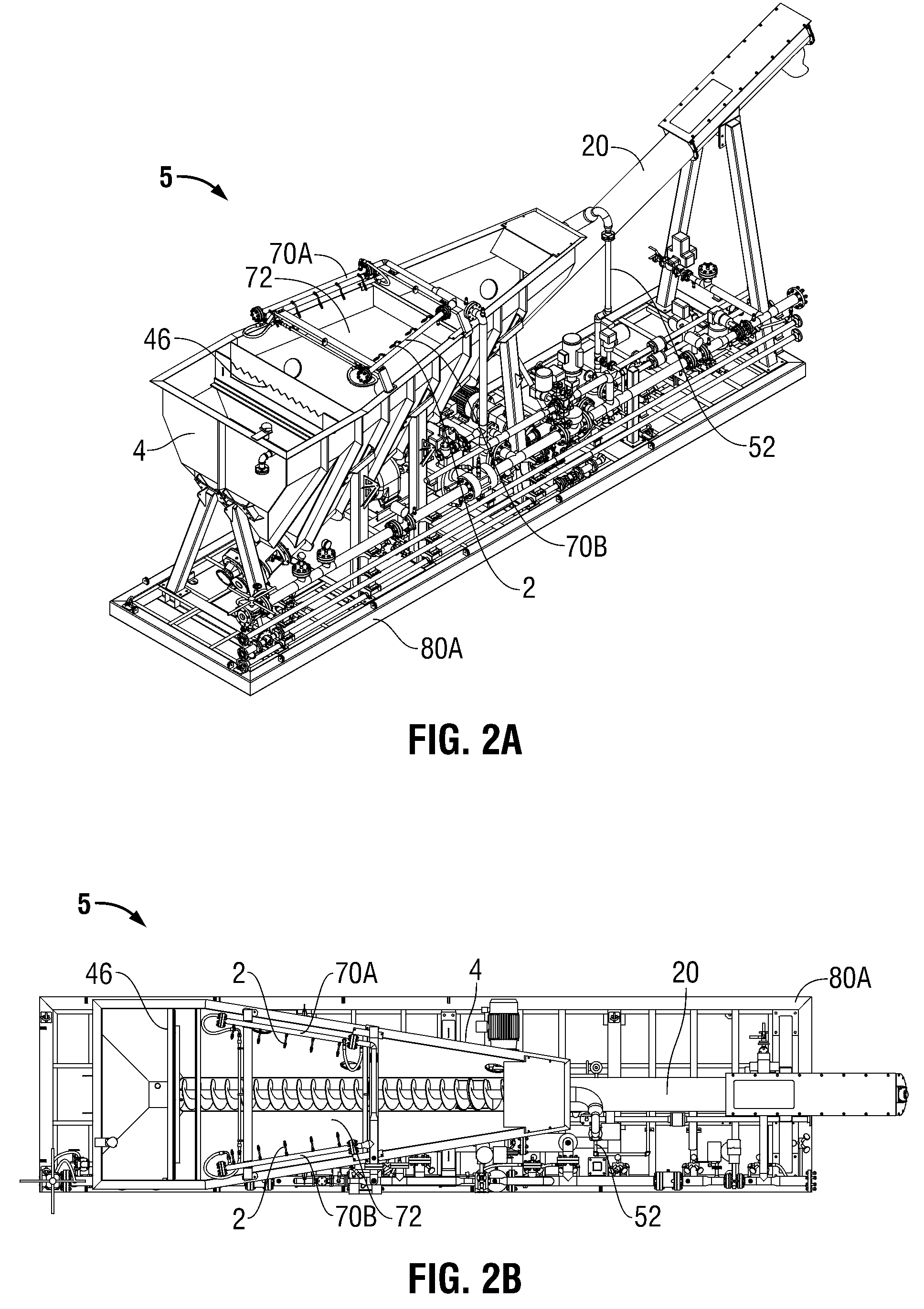
[0040]In FIG. 1, a sulfur seed generating system 5 comprises sulfur seed generating nozzles 2 (shown in detail in FIGS. 2E and 2F) and a cooling or a forming tank 4. The cooling tank 4 may be a spiral dewaterer tank with an angled bottom surface and a screw conveyor or auger 20, as shown in FIGS. 2A to 2D. Other cooling tank configurations are also contemplated. As shown in FIG. 1, liquid sulfur is pumped through a liquid sulfur supply line 14 with a liquid sulfur pump 22. The liquid sulfur may be diverted from the line 14 to a seed sulfur line 26 for delivery to tank 4 through sulfur seed nozzles 2 in spray (or droplet) form. The cooling tank 4 contains a liquid, such as water, to cool and solidify the molten sulfur spray. Other liquids, fluids or coolants are contemplated. Sulfur seeds formed by the interaction of the sulfur spray with the liquid settle in the tank 4. The sulfur seeds produced by the system 5 may be spherical in shape, typically between 0.1 and 2 mm in diameter an...


PUM

PropertyMeasurementUnit
diameteraaaaaaaaaa
diameteraaaaaaaaaa
diameteraaaaaaaaaa

Abstract

Sulfur (or sulphur) spray nozzles disposed with a cooling tank spray liquid molten sulfur into the cooling liquid in the tank. Solid sulfur seeds are formed in the cooling liquid and settle in the tank. The cooling tank may be a spiral dewaterer tank that has a screw conveyor at the bottom of the tank that moves the seeds to a granulating drum for enlargement into sulfur granules. The cooling tank may also be used to capture and remove sulfur dust from a slurry of sulfur dust and water recycled from the granulating drum. The sulfur dust in the cooling tank may be captured by contact with molten sulfur droplets streaming down the cooling liquid column such that the dust particles become incorporated into the droplet, thereby being converted to seed. The granulating drum may be equipped with two or more sets of segmented lifting flights. The sets of flights may not be in alignment. The flights may be spaced apart from the inside surface of the drum with segmented rib members. The rib members may allow for the movement of sulfur seeds and granules between the flights and the inside surface of the drum as the drum rotates.

Description

CROSS-REFERENCE TO RELATED APPLICATIONS[0001]N / ASTATEMENT REGARDING FEDERALLY SPONSORED RESEARCH OR DEVELOPMENT[0002]N / AREFERENCE TO MICROFICHE APPENDIX[0003]N / ABACKGROUND OF THE INVENTION[0004]1. Field of the Invention[0005]This invention relates to the field of converting molten sulfur (or sulphur) into solid sulfur granules using sulfur seeds.[0006]2. Description of the Related Art[0007]Sulfur is an important industrial commodity, most commonly produced in molten liquid form as a byproduct from oil and gas refining. Much of the liquid sulfur is solidified into various “forms,” such as granules, pastilles or prills for ease in transportation and use. The various forms are commercially produced by different processes. Granules are produced by enlarging “seeds” in a granulating drum; pastilles are formed by laying sulfur drops onto a continuous stainless steel belt; and prills are produced by dropping liquid sulfur into a bath of cooling water. Whereas pastilles and prills are produ...

Claims


Application Information

Patent Timeline
Patent Type & Authority Patents(United States)
IPC IPC(8): B29B9/00
CPCB01J2/06C01B17/0216C01B17/0237B01J2/12B01J19/26C01B17/02B29B9/12
Inventor LANG, LESLIE L.LARSON, PAUL R.IRANI, JAMSHEED P.DE PAOLI, SERGIO A.METHERAL, CASEY J.
Owner IPCO US LLC
Learn More