Filtration tray for fixed bed reactor with a co-current down-flow of gas and liquid

a technology of co-current downflow and filtration tray, which is applied in the direction of hydrocarbon oil cracking, chemistry apparatus and processes, organic chemistry, etc., can solve the problems of not providing a system for controlling or independent gas flow, reducing process run time, and no re-distribution device is provided

Active Publication Date: 2012-12-11
INST FR DU PETROLE
View PDF16 Cites 16 Cited by
  • Summary
  • Abstract
  • Description
  • Claims
  • Application Information

AI Technical Summary

Problems solved by technology

The pressure drop may become such that the operator is obliged to shut down the reactor and replace all or part of the catalyst, which clearly considerably reduces the run times of the process.
Further, the plugging particles may be deposited in the bed in a more or less random manner and result in heterogeneities in the distribution of the void fraction of that bed which result in the creation of preferred pathways.
Such preferred pathways are major problems from the hydrodynamic viewpoint as they can substantially perturb the homogeneity of flow of the phases in the bed and may contribute to heterogeneities in the progress of the chemical reaction, as well as thermal considerations.
The inlet to the conduits is located upstream or downstream of a distributor tray, but no system is provided for deflecting the liquid flow and the gas flow in a controlled or independent manner.
No re-distribution device is provided in this case to homogenize the flow at the outlet from the conduits.
This device also suffers from the disadvantage of being sensitive to sudden pressure variations.
In this case, a non-negligible volume of the bed is occupied by said baskets which do not actually prevent fouling of the fractions of the bed located between the baskets.
Further, for gas / liquid flow applications, the system cannot control a homogeneous distribution of the gas / liquid flow between the baskets and downstream of the baskets.
In the article by T H Lindstrom et al in Hydrocarbon Processing, February 2003 (pages 49-51), a system of external filters is described, but that system does not overcome all types of blockage and the cost of that solution is very high.
The device described in the cited patents cannot control the ratio between the liquid flow and the gas flow deflected into the tubes composing said system.
Further, there is no fluid distribution effect at the outlet from the devices described in the two cited patents, necessitating the downstream provision of a distributor tray or an equivalent system.
That device does not include an effective system for re-distribution of gas / liquid effluents at the outlet from said chambers when the system is used in gas / liquid flow mode.

Method used


Image

  • Filtration tray for fixed bed reactor with a co-current down-flow of gas and liquid
  • Filtration tray for fixed bed reactor with a co-current down-flow of gas and liquid
  • Filtration tray for fixed bed reactor with a co-current down-flow of gas and liquid

Examples


example

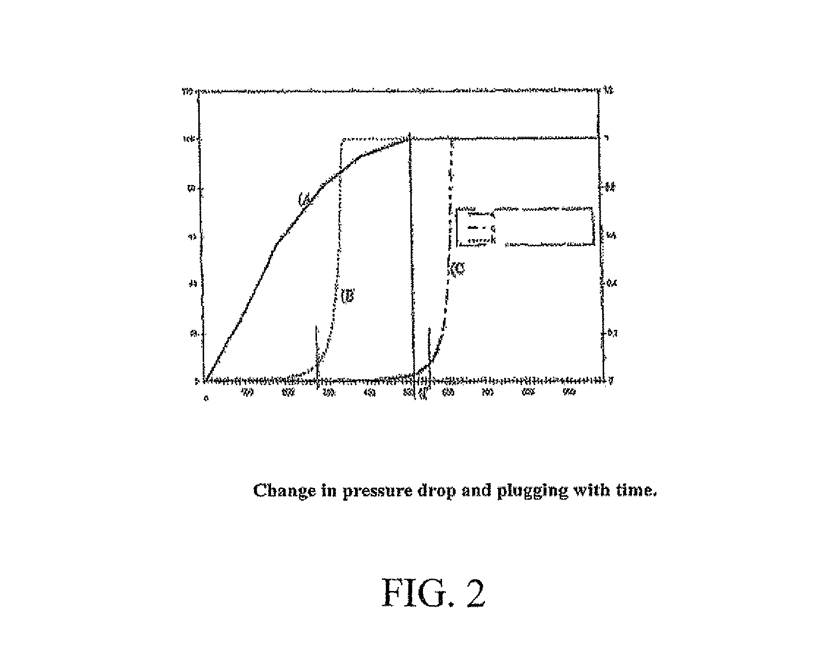
[0105]The following example derives from a simulation using a kinetic equation for the deposition of particles which corresponds to a linear deposition as a function of time.

[0106]The reactor had a diameter of 1 metre and a total height of 5 metres including the distributor tray and the catalytic bed. The catalytic bed was composed of particles of a traditional catalyst to carry out selective hydrogenation. It was a catalyst containing Ni deposited on an alumina support.

[0107]The particle size of the catalyst forming the catalyst bed located downstream of the distributor tray was 2 mm.

[0108]The reactor was supplied with a liquid portion and a gas portion.

[0109]The liquid was constituted by a pyrolysis gasoline with a boiling point range in the range from 50° C. to 280° C. with a mean boiling point of 120° C. under standard conditions. The gas phase was composed of 90 mole % hydrogen, the remainder being essentially methane.

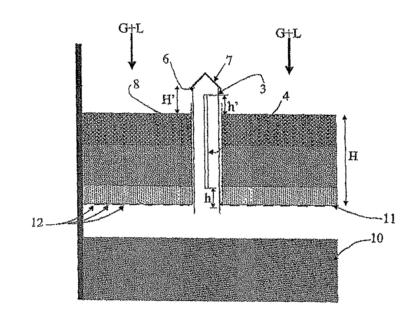
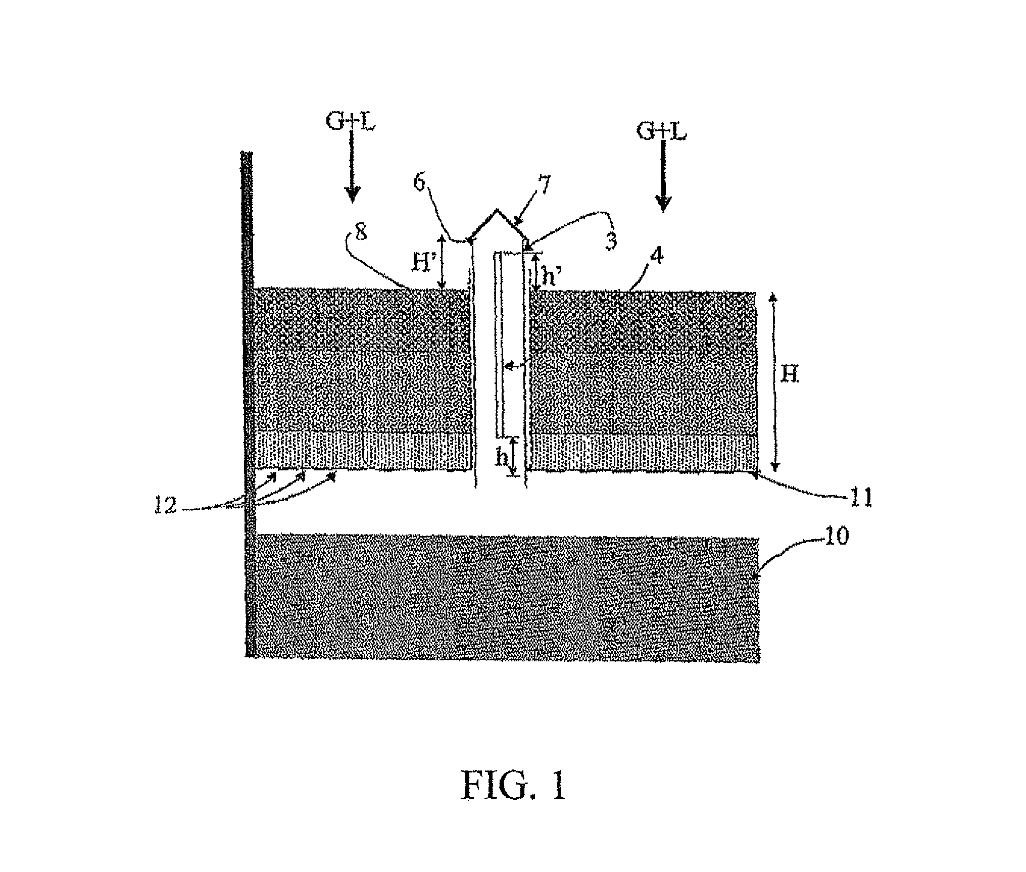
[0110]The filtering distributor tray had 7 chimneys with a d...


PUM

PropertyMeasurementUnit
total heightaaaaaaaaaa
heightaaaaaaaaaa
particle sizeaaaaaaaaaa

Abstract

The device described in the present invention can trap plugging particles contained in the liquid feed supplying a reactor functioning in gas and liquid co-current down-flow mode using a specific distributor tray comprising a filtration medium.The present device is of particular application to the selective hydrogenation of feeds containing acetylenic and dienic compounds.

Description

FIELD OF THE INVENTION[0001]The invention relates to the field of distributor trays intended to supply chemical reactors functioning in gas and liquid co-current down-flow mode with gas and liquid.[0002]Such reactors are encountered in the refining field, more particularly in the selective hydrogenation of various oil cuts, and more generally in hydrotreatments which require high pressure hydrogen streams operating with heavy liquid feeds which may contain impurities constituted by plugging solid particles.[0003]In some cases, the liquid feed contains impurities which may be deposited on the catalytic bed itself and over time may reduce the interstitial volume of that catalytic bed.[0004]Plugging feeds which may be cited include mixtures of hydrocarbons containing 3 to 50 carbon atoms, preferably 5 to 30 carbon atoms, which may contain a non-negligible proportion of unsaturated or polyunsaturated acetylenic or dienic compounds or a combination of those various compounds, the total p...

Claims


Application Information

Patent Timeline
Patent Type & Authority Patents(United States)
IPC IPC(8): C07C7/00
CPCB01J8/0085B01J8/025B01J8/0278B01J8/0453C10G49/002B01J8/0242B01J8/0492C10G2300/1077B01J2208/00371C10G2300/107C10G49/00B01J8/02B01J8/04
Inventor KOUDIL, ABDELHAKIMBOYER, CHRISTOPHE
Owner INST FR DU PETROLE
Why Eureka
Try Eureka