

Battery voltage monitoring apparatus
a battery voltage and monitoring device technology, applied in the direction of alarms, instruments, transportation and packaging, etc., can solve the problems of unstable output and inability to detect disconnection
- Summary
- Abstract
- Description
- Claims
- Application Information
AI Technical Summary
Benefits of technology
Problems solved by technology
Method used
Image

Examples
first embodiment
[0030][First Embodiment]
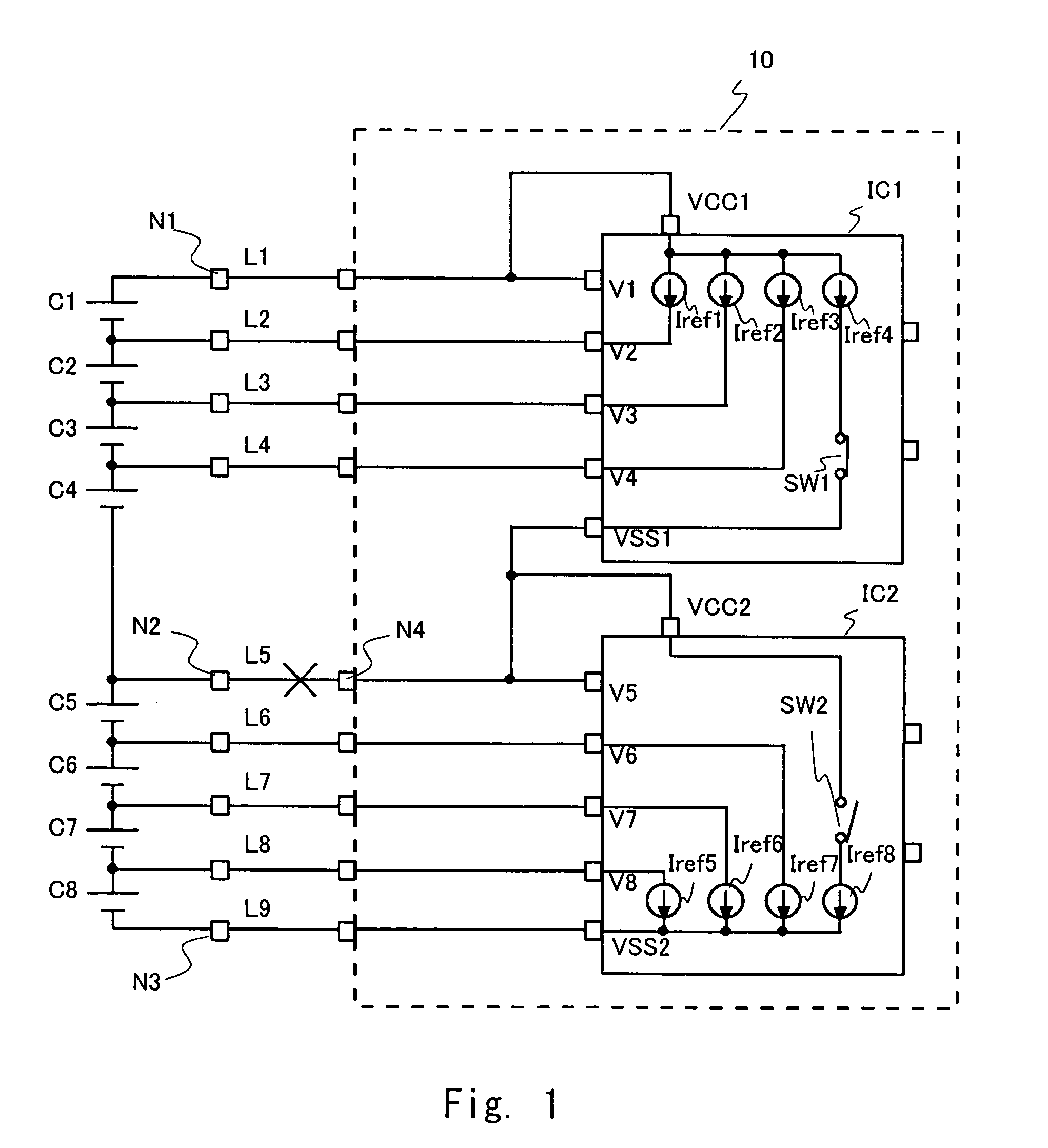
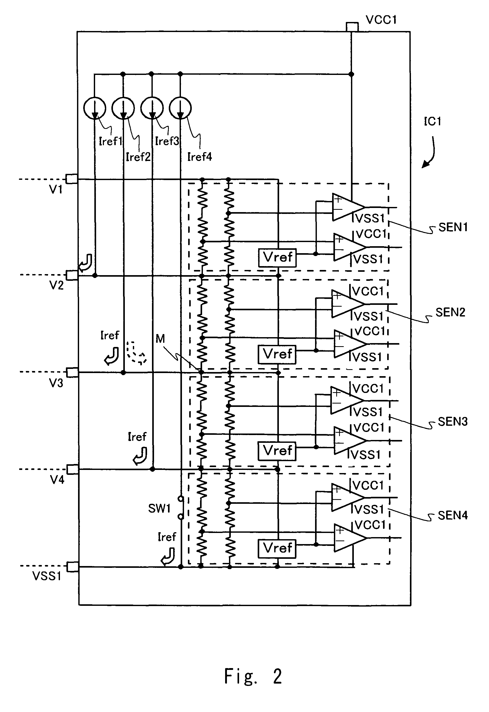
[0031]Hereinafter, embodiments of this invention are described with drawings. FIG. 1 shows a schematic diagram for explaining a voltage monitoring apparatus 10 according to the first embodiment of the invention. The voltage monitoring apparatus 10 of this embodiment includes a plurality of voltage sensor modules. Here, the voltage sensor module is defined as an electrical element including one or more voltage sensors. In this embodiment, one module is configured as one semiconductor device (IC). FIG. 1 shows an instance of the voltage monitoring apparatus 10 including two voltage sensor modules IC1 and IC2. Hereinafter, the voltage sensor module is also called IC. Hereinafter, with taking a case in which one IC detects four battery cell voltages as an example, a first embodiment will be described.
[0032]As FIG. 1 shows, in this embodiment, eight battery cells C1-C8, which are objects to be monitored by the voltage monitoring apparatus, are connected in series....
second embodiment
[0051][Second Embodiment]
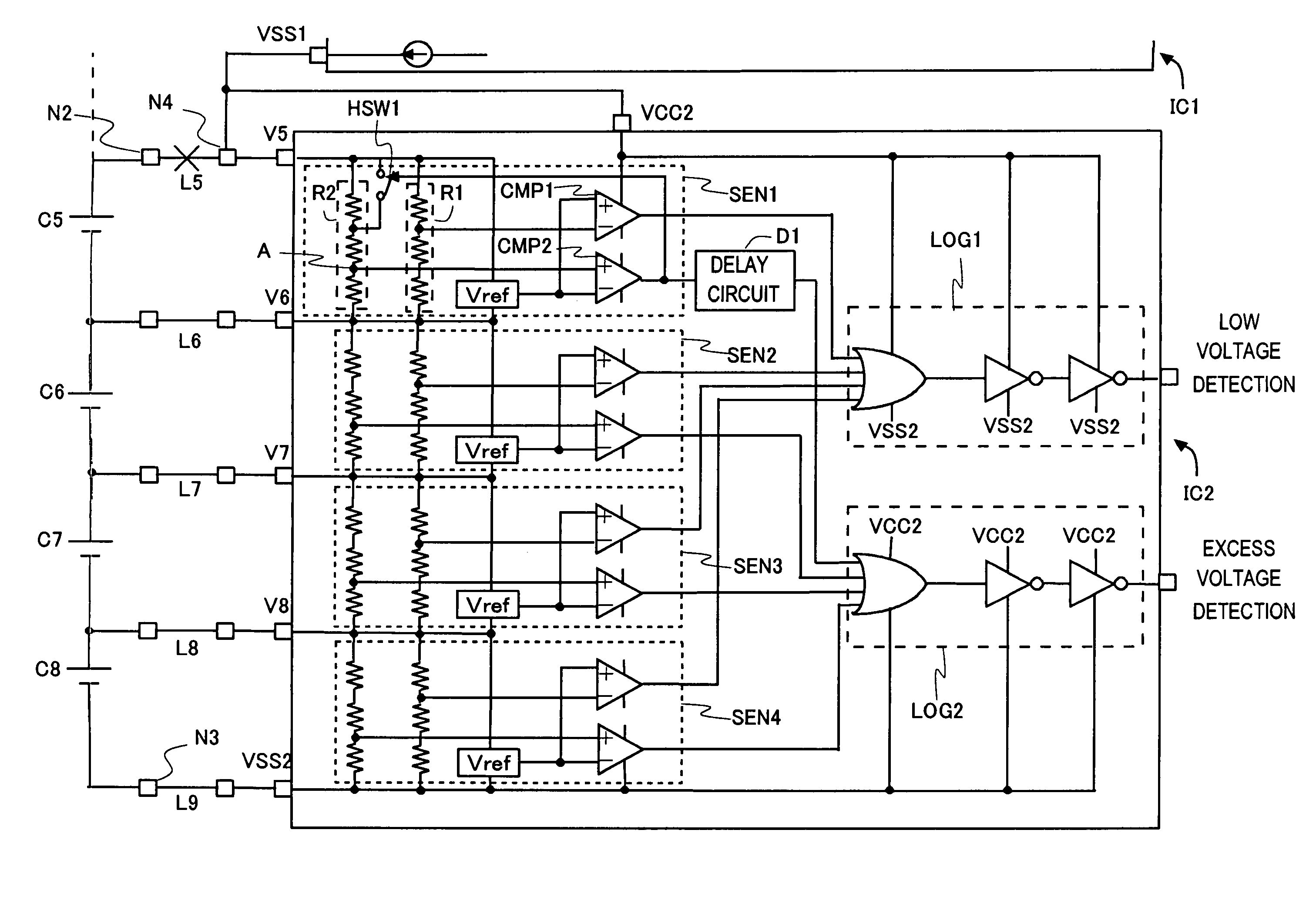
[0052]FIG. 5 shows a voltage monitoring apparatus according to a second embodiment in this invention. FIG. 5 shows the voltage monitoring apparatus of second embodiment comprising IC3, which has the same configuration as IC1, connected to the IC2 of FIG. 1 and FIG. 3. Hereinafter, the case will be explained in witch disconnection is caused in a line L9 corresponding to the connect portion between IC2 and IC3 in this voltage monitoring apparatus 20.
[0053]When the line L9 comes down, current from positive terminal of battery cell C9 does not flow into current sources Iref9-Iref12 of IC3. When disconnection is caused in the line L9, current from VSS2 terminal (node N5) flows into Iref9-Iref12. Hence, VSS2 terminal potential becomes lower and potential between V8 and VSS2 in IC2 becomes larger. As a result, a voltage sensor connected between V8 and VSS2 of IC2 detects excess voltage and outputs the excess voltage detect signal. This embodiment prevents false ope...
embodiment 1
[0061][Variant Embodiment 1]
[0062]FIG. 8 shows a variant embodiment of voltage monitoring apparatus according to embodiments of this invention. The variant also has function of detecting disconnection. This embodiment differs from the first and the second embodiments in the way of detecting disconnection. In the voltage monitoring apparatus shown in FIG. 8, a resistor is connected between input terminals of voltage sensor. The value of resistor R3 connected between input terminals of voltage sensor SEN1 is different from the value of resistor R4 connected between input terminals of voltage sensor SEN2. The resistors R3 and R4 are connected alternately between input terminals of the other voltage sensors below.
[0063]Hereinafter, operation of detecting disconnection in the voltage monitoring apparatus configured as described above is explained. The resistor R4 having low resistance value is connected to a forth voltage sensor which is not shown of IC1. The resistor R3 having high resi...
PUM
| Property | Measurement | Unit |
|---|---|---|
| voltage | aaaaa | aaaaa |
| reference voltage | aaaaa | aaaaa |
| hysteresis | aaaaa | aaaaa |
Abstract
Description
Claims
Application Information