[0006]Thus, it would be advantageous to develop a method and an apparatus for calibrating a sensor circuit to cancel out (or ignore)
contamination deposited on a sensor that is repeatedly immersed in water during normal operations or providing an adjustable pump down (or activation) time to accommodate different applications. Regular calibration of the sensor circuit reduces the need for cleaning of the sensor which may be placed in a remote or hard to reach location (e.g., inside a
transformer vault or an
elevator shaft). The adjustable pump down time may be changed in the field or by a user to account for different pumps or sizes of enclosed space.
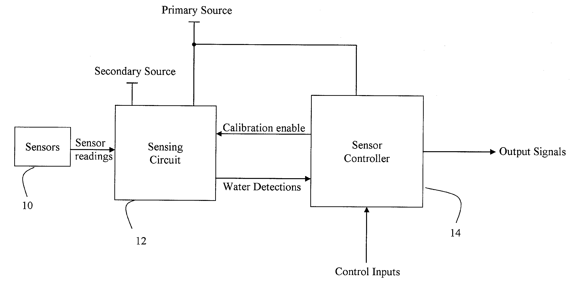
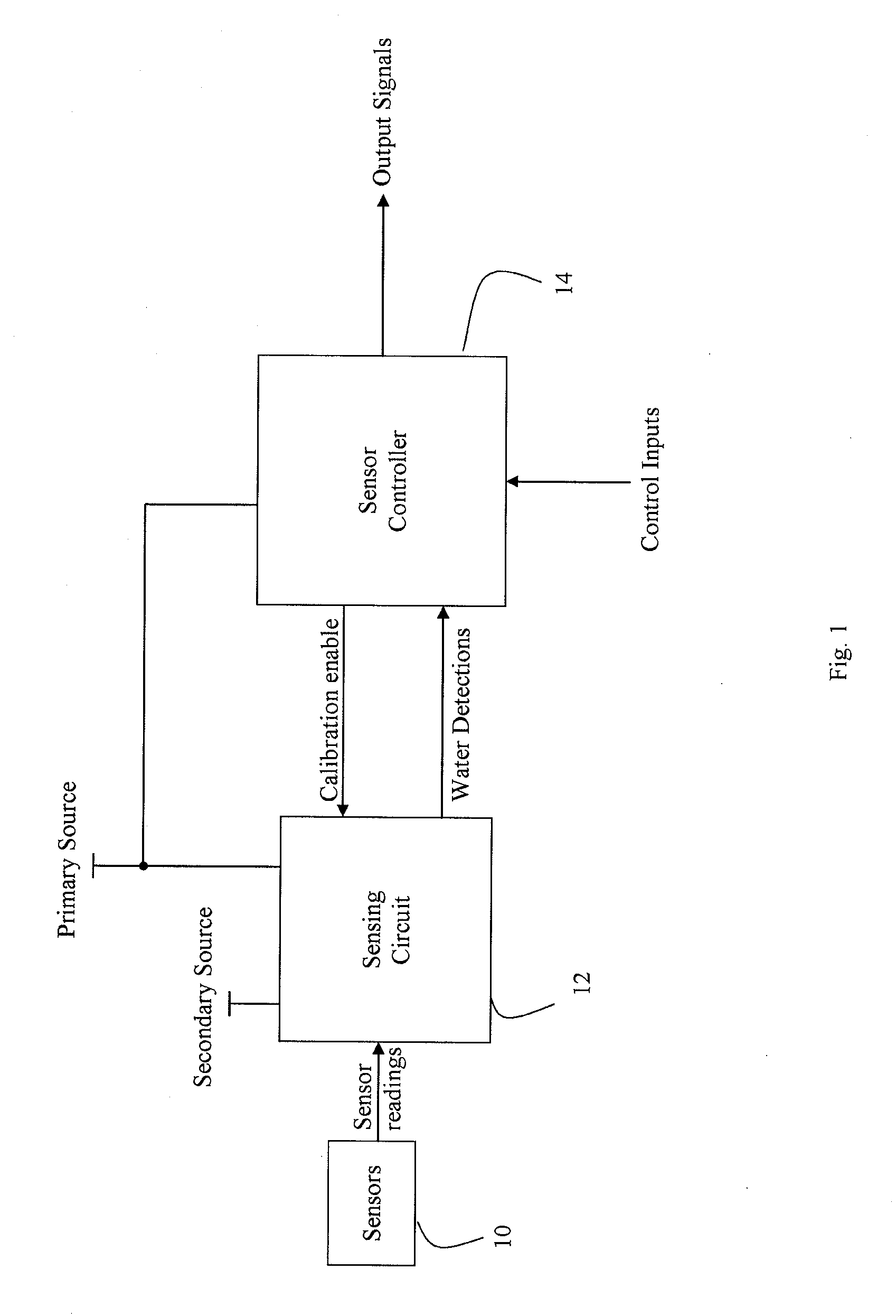
[0008]The self-calibrating sensing circuit is configured to receive the sensor reading from the electronic sensor and to generate a water detection
signal to indicate whether the electronic sensor is immersed in
water based on the sensor reading. During calibration, the self-calibrating sensing circuit improves accuracy of the water detection
signal by adjusting one or more internal parameters to null an effect on the sensor reading due to contaminants or non-water substances in contact with the electronic sensor. That is, the self-calibrating sensing circuit reduces its sensitivity to any substance that is in contact with the electronic sensor during calibration.
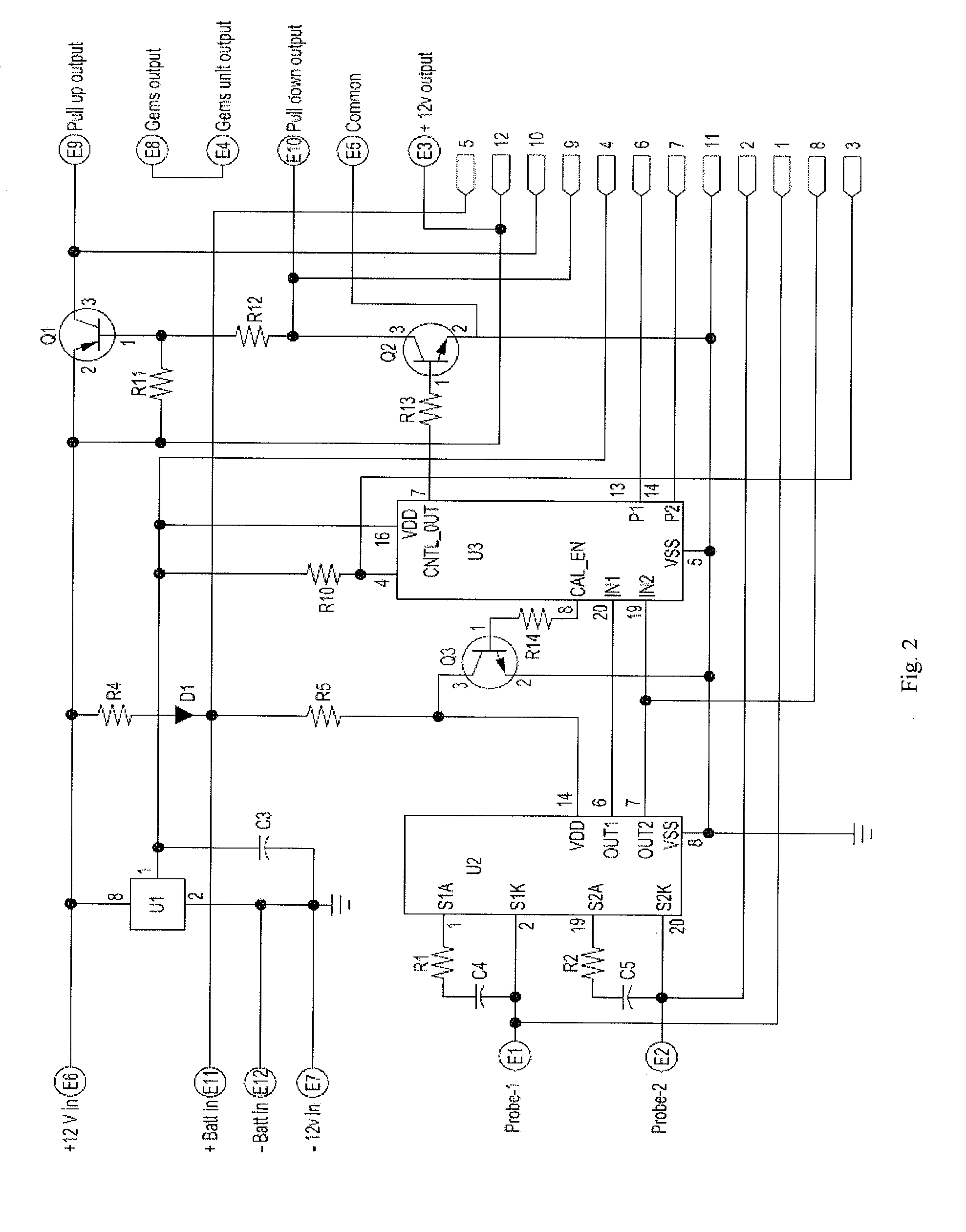
[0011]In one embodiment, the sensor controller is implemented with a
microcontroller chip. The
microcontroller chip includes programmable input / output ports and a
microprocessor. The
microcontroller chip can be programmed to run different calibration algorithms and to generate different control output signals for different applications. In one application, the water detection signal is provided to an input of the microcontroller chip and a
calibration algorithm uses one or more timers to generate a pulse signal to periodically trigger calibration in the self-calibrating sensing circuit while the water detection signal does not indicate that the electronic sensor is immersed in water. In some instances, timers (e.g., counters) in the microcontroller chip may have an upper limit and thus limit a trigger period for calibration. A
cascade of two or more timers can be used to lengthen the trigger period (i.e., increase an interval between calibrations).
[0012]In one application, a control output signal is configured to activate an alarm (e.g., a light or a sound) when the water detection signal indicates that the electronic sensor is immersed in water. For example, the alarm may be used to inform a remote
monitoring system of possible problems (e.g., a failed pump) in a dewatering system or to provide visual and audible aid to personnel in the vicinity regarding a status of the dewatering system. In another application, a control output signal is configured to activate a water pump while the water detection signal indicates that the electronic sensor is immersed in water. The control output signal may optionally be configured to continue activating the water pump for a predetermine duration (e.g., eight seconds) after the
water detector signal indicates that the electronic sensor is no longer immersed in water. The predetermined duration can be variable (e.g., from seconds to minutes by
programming the microcontroller chip) and can be set according to a type of water pump being used, an
enclosure's size, and the like. Allowing the water pump to remain active for the predetermined duration after the electronic sensor is no longer immersed in water avoids frequent on / off cycles for the water pump. For example, if the water pump turns off immediately (or relatively too quickly) after the electronic sensor is no longer immersed in water, the electronic sensor remains relatively close to the
water level and a relatively small amount of additional water or a physical disturbance may trigger the water pump to become active again.
[0018]In some applications, the dewatering system further includes a high liquid alarm system with one or more sensors configured to detect for presence of liquid at a level in the container that is above the first level and the second level. The high liquid alarm system sets off a local alarm or a remote alarm to alert of possible abnormal conditions. For example, water does not normally rise pass the second level unless the water pump is not functioning properly. Other abnormal conditions that can trigger an alarm include excess non-water liquids, such as oil, filling the container. In one embodiment, the high liquid alarm system uses at least one
capacitance sensor with its own self-calibrating sensor circuit to provide reliable and substantially maintenance-free operations.
[0023]In one embodiment, a method for calibrating a sensor comprises providing a first sensor reading from a first
capacitance sensor to a sensing circuit and comparing the first sensor reading with a first reference sensing level in the sensing circuit to generate a first water detection signal that indicates whether the first
capacitance sensor is immersed in water. The method further comprises executing a
calibration algorithm that disables calibration of the sensing circuit when the first water detection signal indicates that the first capacitance sensor is immersed in water and selectively enables calibration of the sensing circuit when the first water detection signal does not indicate that the first capacitance sensor is immersed in water. The first reference sensing level is adjusted during calibration to effectively cancel errors in the first sensor reading due to accumulative
contamination deposited on the first capacitance sensor. The first water detection signal can also be used to generate an output signal to control a water pump or an alarm in a dewatering system.
