Signal control elements in ferromagnetic logic

a ferromagnetic logic and signal control technology, applied in the field of nanoscale ferromagnets, can solve the problems of significant direction control, noise/error, external fields of the magnet, etc., and achieve the effects of high anisotropy energy, lower anisotropy energy, and high anisotropy energy nanomagnets

Inactive Publication Date: 2012-12-11
GLOBALFOUNDRIES INC
View PDF11 Cites 2 Cited by
  • Summary
  • Abstract
  • Description
  • Claims
  • Application Information

AI Technical Summary

Problems solved by technology

Although each nanomagnet is a nonvolatile element that can store information, the magnets can each be disturbed by noise / error and external fields.
As a logic signal can propagate in the forward or backward direction in a chain of nanomagnets, direction control is a significant challenge.

Method used


Image

  • Signal control elements in ferromagnetic logic
  • Signal control elements in ferromagnetic logic
  • Signal control elements in ferromagnetic logic

Examples


Embodiment Construction

[0025]Nanomagnets made of different materials have different properties. For example, the following table shows different parameters (e.g., anisotropy energy constant) of different metallic ferromagnetic materials.

[0026]

EasySaturationTC(K)axisMag. (Ms)Anisotropy (Ku)Fe (bcc)1043[100]1.74 × 10⁶ A / m5.42 × 104 J / m3Co (hcp)1388c-axis1.47 × 106 A / m7.71 × 105 J / m3Ni (fcc)631[111]1.26 × 10⁵ A / m1.26 × 105 J / m3[0027]It is also possible to modulate the key material parameters by doping semiconductors and oxides differently with ferromagnetic species (e.g., Mn).

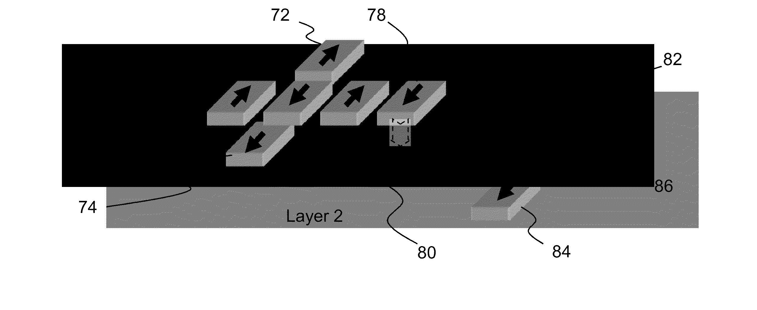
[0028]Anisotropy energy determines how hard it is to switch a nanomagnet. Nanomagnets made of different materials can be inserted in a ferromagnet logic system. As shown in FIG. 4(a), nanomagnet 10 has a higher anisotropy constant, as indicated by a darker tone, than the other nanomagnets in the chain. In FIG. 4(b), nanomagnet 14 has a lower anisotropy constant, as indicated by a lighter tone, than the other magnets in the chain. Since ...


PUM


Abstract

A chain of field coupled nanomagnets includes at least one elements having substantially different anisotropy energy from that of the other nanomagnets. A signal can propagate from a first input nanomagnet having a relatively high anisotropy energy through the chain to an output nanomagnet. The output nanomagnet may have a relatively lower anisotropy energy than the other nanomagnets. Signal flow direction thus can be controlled. The higher anisotropy energy nanomagnet may be attained by use of a ferromagnet material having a higher anisotropy constant and / or configured with a larger volume than the other elements. The lower anisotropy energy magnet may be attained by use of a ferromagnet material having a lower anisotropy constant and / or configured with a smaller volume than the other elements. Logic signal flow control can also be attained making use of three dimensional geometries of nanomagnets with two different orientations.

Description

BACKGROUND[0001]The present disclosure relates to nano-scale ferromagnets (nanomagnets), and more particularly to use of ferromagnet logic systems in sequential logic applications.[0002]With CMOS scaling approaching fundamental limits, emerging logic devices based on novel state variables are considered promising candidates for beyond-CMOS computation solutions. So-called spintronic devices can be used to implement binary logic functionality. Magnetic anisotropy is a directional dependence of the magnetic properties of the magnet material. The magnetization direction of nanomagnets is the collective polarization direction of all the spins inside of the magnets. Rectangular or elliptical shaped nanomagnets have lower energy when the magnetization direction is along the long side of the magnet configuration than when the magnetization direction is along the short side. The magnetic material will align its magnetic moment to the lower energy long direction, commonly referred to as the ...

Claims


Application Information

Patent Timeline
Patent Type & Authority Patents(United States)
IPC IPC(8): G11C11/15H03K19/168
CPCB82Y10/00B82Y25/00H03K19/168
Inventor CHEN, ANKRIVOKAPIC, ZORAN
Owner GLOBALFOUNDRIES INC
Why Eureka
Try Eureka