Apparatus for and method of separating multi-phase fluids

a multi-phase fluid and apparatus technology, applied in the direction of liquid separation, chemistry apparatus and processes, single direction vortex, etc., can solve the problems of erratic and variable flow of multi-phase fluids entering the separator, large size and fluid inventory, and inability to meet the needs of additional pipework, so as to avoid the need for additional pipework and compact unit

Inactive Publication Date: 2012-12-18
CALTEC
View PDF14 Cites 6 Cited by
  • Summary
  • Abstract
  • Description
  • Claims
  • Application Information

AI Technical Summary

Benefits of technology

[0015]The cyclonic separator and the secondary separator work together to provide greater efficiency in the separation of gas and liquid phases and an increased capability to handle flow fluctuations and slugging. The cyclonic separator serves as a flow stabiliser and flow conditioner and provides for bulk separation of the gas and liquid phases, which eliminates the need for a long liquid residence time in the secondary separator. The secondary separator then removes any liquid carried over in the separated gas and any gas carried over with the separated liquid, and removes any fine liquid droplets carried through with the gas phase. The removal of mist is achieved by reducing velocity of the gases as they enter the separator, which causes the droplets to settle out of the gas phase, and by directing those fluids along the peripheral wall of the vessel so that the droplets coalesce and form a film of liquid that runs down the wall into the lower part of the vessel. The apparatus is more compact than conventional separation systems, has significantly increased turn-down capacity and accommodates an increased flow rate range for each fluid phase.
[0023]Advantageously, the cyclonic separator is a uniaxial cyclonic separator, the inlet for multi-phase fluids being located at one end of the cyclonic separation chamber and the first and second outlets being located at an opposite end of the cyclonic separation chamber, so that the fluids flow in the same direction (uniaxially) through the separation chamber. A uniaxial cyclonic separator provides greater separation efficiency than other types of cyclonic separator such as hydrocyclones and it is better able to cope with fluctuations in the flow regime. Preferably, the inlet of the cyclonic separator includes an involute inlet chamber, the first outlet of the cyclonic separator for relatively high density fluids includes an involute outlet chamber, and the second outlet of the cyclonic separator for relatively low density fluids includes an axial outlet conduit.
[0024]Advantageously, the cyclonic separator is located within the separation vessel. This provides a compact and integrated device that only requires connections to be made to the inlet for multiphase fluids and the outlets for the separated gas and liquid phases. Installation is therefore simple and efficient. A further advantage is that the cyclonic separator does not then have to be designed to withstand the full inlet pressure, since it will only be subjected to the relatively small differential pressure between its internal pressure and the internal pressure of the secondary separator.
[0026]Advantageously, the first outlet and / or the second outlet of the cyclonic separator is connected to a supplementary cyclonic separator comprising a vertically-arranged tube having an upper end that opens into an upper part of the separation vessel and a lower end that opens into a lower part of the separation vessel, which holds the liquid phase. The secondary cyclonic separator helps to remove carry-over in the outlet fluids of the main cyclonic separator and also reduces turbulence and fluid splashing within the secondary separator.
[0027]The apparatus may include a plurality of cyclonic separators connected to a smaller number of secondary separators. The apparatus preferably includes one or more manifolds connecting the outlets of the cyclonic separators to the inlets of the secondary separator(s). The apparatus may include one or more manifolds connected to the inlets of the cyclonic separators for delivering the multi-phase fluids to the cyclonic separators. The apparatus may include means for controlling the flow of fluids through the cyclonic separators. This allows the capacity of the system to be varied easily while using components of standard sizes.
[0040]The secondary separator preferably resembles a knock-out vessel. The cyclonic separator may be located within the secondary separator, so avoiding the need for additional pipework and providing a highly compact unit. Alternatively, the cyclonic separator may be located outside the secondary separator with the outlets of the cyclonic separator feeding into the secondary separator at different locations.

Problems solved by technology

The main disadvantages of conventional gravity separators are their size and large fluid inventory, which is an important safety issue in case of explosion or fire.
A saving in space and weight is therefore an important issue, particularly on offshore platforms.
However, in many cases the flow of multi-phase fluids entering the separator is erratic and variable in terms of both consistency and the instantaneous flow rate of the gas and liquid phases.
Typically, if the mixture flow rate drops below one fifth of the designed flow rate, the performance efficiency of the unit drops because it can no longer generate sufficiently high “g” forces for efficient cyclonic separation of the liquid and gas phases.
Fluctuations in the flow rate affect the efficiency of all separators, but compact cyclonic separators are even more sensitive to variable flow regimes because of their compactness.
However, complete separation of gases and liquids is rarely achieved.
This apparatus therefore reduces the amount of liquid carried over in the gas phase, but does not prevent gases from being carried over in the liquid phase.
In certain applications this may be unacceptable.
Furthermore, because the separation process is carried out mainly by the cyclonic separator, the apparatus does not address the problems caused by variable flow regimes, which may prevent efficient operation of the cyclonic separator.

Method used


Image

  • Apparatus for and method of separating multi-phase fluids
  • Apparatus for and method of separating multi-phase fluids
  • Apparatus for and method of separating multi-phase fluids

Examples


Embodiment Construction

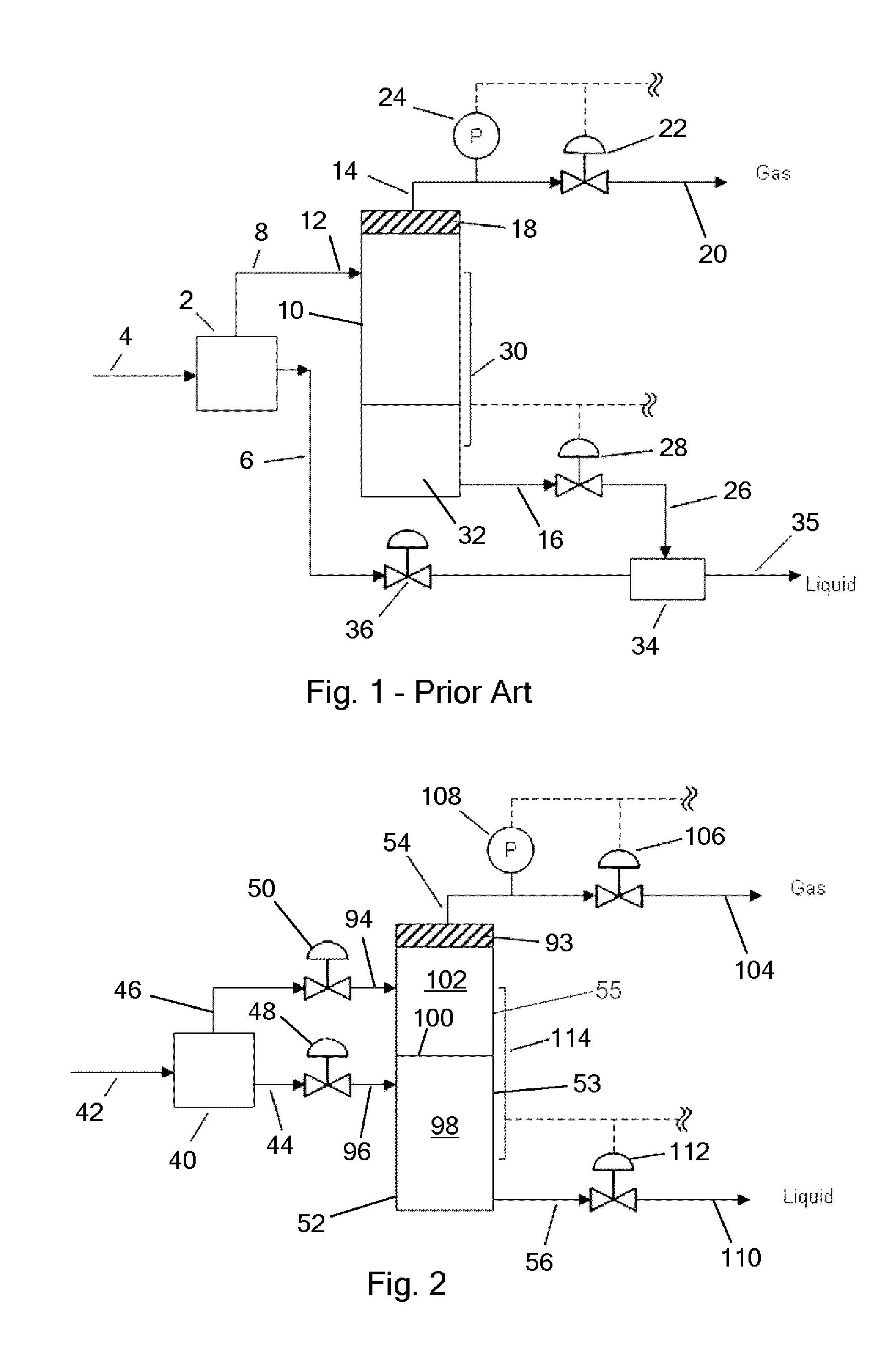
[0055]FIG. 1 shows a prior art compact separation system. The system includes a compact uniaxial cyclonic separator 2 having an inlet line 4 for multi-phase fluids, a first outlet line 6 for relatively high density fluids (primarily liquid) and a second outlet line 8 for relatively low density fluids (primarily gas). The second outlet line 8 is connected to a conventional knock-out vessel 10. This consists of a cylindrical vessel that is mounted with its longitudinal axis vertical. The vessel has an inlet 12 that is connected to receive the low density fluids from the cyclonic separator 2, a first outlet 14 at its upper end for gas and a second outlet 16 at its lower end for liquid. The knock-out vessel 10 also includes a mist extractor 18 at its upper end for removing mist from the gas flowing towards the gas outlet 14.

[0056]The first outlet 14 is connected to a gas outlet line 20, the pressure of gas being controlled by an adjustable valve 22 that may be operated automatically dep...


PUM

PropertyMeasurementUnit
angleaaaaaaaaaa
angleaaaaaaaaaa
diameteraaaaaaaaaa

Abstract

An apparatus for separating multi-phase fluids, comprising a cyclonic separator (40) having an inlet (42) for multi-phase fluids, a cyclonic separation chamber, a first outlet (44) for relatively high density fluids and a second outlet (46) for relatively low density fluids, and a secondary separator (52) comprising a separation vessel in which fluids are separated primarily by gravity, a first inlet (96) connected to receive the relatively high density fluids, a second inlet (94) connected to receive the relatively low density fluids, a first outlet (54) in the upper part of the vessel for a separated gas phase and a second outlet (56) in the lower part of the separation vessel for a separated liquid phase.

Description

RELATED APPLICATIONS[0001]This application is the U.S. National Phase filing under 35 U.S.C. §371 of PCT / GB2008 / 003364, filed Oct. 6, 2008, entitled “Apparatus for and Method of Separating Multi-Phase Fluids”, which designated the United States and was published in English on Apr. 16, 2009, which claims priority under 35 U.S.C. §119(a)-(d) to Great Britain Application No. 0719980.5, filed Oct. 12, 2007, the entire content of which is incorporated herein by reference.FIELD OF THE INVENTION[0002]The present invention relates to an apparatus for and a method of separating multi-phase fluids. In particular, but not exclusively, it relates to a method and apparatus for separating gas and liquid phases in the oil and gas industry.BACKGROUND OF THE INVENTION[0003]In the oil and gas industry, the fluids extracted from a well often consist of a mixture of gas and liquid. Separation of gas and liquid phases is normally carried out using conventional gravity separators. These are large horizon...

Claims


Application Information

Patent Timeline
Patent Type & Authority Patents(United States)
IPC IPC(8): B01D19/00
CPCB01D17/0217B01D19/0057B01D19/0094B04C3/00B04C9/00
Inventor SARSHAR, MAHMOOD MIRBEG, ALI NAJAM MIRAZNALUKURTHY, RAJA KISHORE
Owner CALTEC
Why Eureka
Try Eureka