Fuel saving method and device for vehicle

a fuel saving and vehicle technology, applied in the direction of machines/engines, liquid/fluent solid measurement, process and machine control, etc., can solve the problems of altering the amount of power the engine delivers, changing the p/f ratio, etc., to improve the usability of the system, reduce the impact of vehicle speed, and increase the range of vehicle speeds

Active Publication Date: 2012-12-25
HE JING +1
View PDF32 Cites 43 Cited by
  • Summary
  • Abstract
  • Description
  • Claims
  • Application Information

AI Technical Summary

Benefits of technology

[0027]This “on and off” or PWM approach, if left to the driver to enact, would probably feel unnatural and cumbersome. Accordingly, in a more preferred embodiment, a third aspect of the invention is used, i.e., letting the system operate the throttle to control the pulse and glide phases automatically, which is an especially significant enhancement to the usability of the system. For the convenience of the driver, the system operates the throttle with a throttle actuator to control the engine's output and to induce the engine into running in its most efficient state.
[0028]The accelerator pedal's relative position serves as a signal to the system for the speed the driver desires to drive at, and the system can adjust the durations of the pulse phase and the glide phase to maintain the vehicle running at the speed the pedal position indicates. This method of delivering engine power to control vehicle speed is analogous to using PWM to deliver electrical power. Modulating the length of the pulse phase allows varying amounts of acceleration to be delivered to the vehicle to achieve a large range of vehicle speeds. Should the driver have need for acceleration even faster than what the engine can provide at optimal efficiency, the driver need only push the accelerator pedal beyond a certain point, past which the system surrenders control of the throttle to the driver allowing the driver to accelerate the vehicle as desired. In this way, the system automatically operates the vehicle as fuel efficiently as possible with alternating pulse and glide phases but will not impede the vehicle's performance when the driver demands more performance.
[0029]The system provides a new and innovative way of managing the energy that the engine produces. This system saves fuel, and functions universally well on any vehicle. The system does not have need for any pre-stored data regarding the engine's most efficient region since the system can find the most efficient state dynamically regardless of the model of the engine. The system can induce the engine to work in the most fuel efficient state nearly all the time. It is furthermore convenient for drivers to use, as they do not have to alter their driving habits to gain the benefits of improved fuel economy with the system.
[0030]Another advantage is that it is easy to integrate this system into any consumer vehicle manufactured after 1996, when OBD-II protocols were made standard. With the possible exception of a brake pedal sensor to sense pedal position, all the hardware and interconnections that the system needs can be found as standard components already on-board most vehicles. Therefore, for most vehicles, adding the system can be as simple as reprogramming the vehicle's electronic control module (“ECM”), since the hardware (such as the sensors and the throttle actuator) and the network infrastructure linking these components together already exist on-board the vehicle.
[0031]The system can be installed as a plug-in add-on device, but part of the beauty of the system is that it can also be inexpensively integrated into the vehicle, adding no extra hardware but simply reprogramming the vehicle to make better use of the equipment it already has and thereby improving fuel economy. Test-drive experiments with the prototype have shown that this system can make the vehicle's fuel economy approach (and under some circumstances such as highway speeds even exceed) that of comparable hybrids, but at a much lower cost of upgrade.

Problems solved by technology

Inducing a transmission gear shift also induces a change in the P / F ratio because this alters the amount of power the engine delivers.

Method used


Image

  • Fuel saving method and device for vehicle
  • Fuel saving method and device for vehicle
  • Fuel saving method and device for vehicle

Examples


Embodiment Construction

)

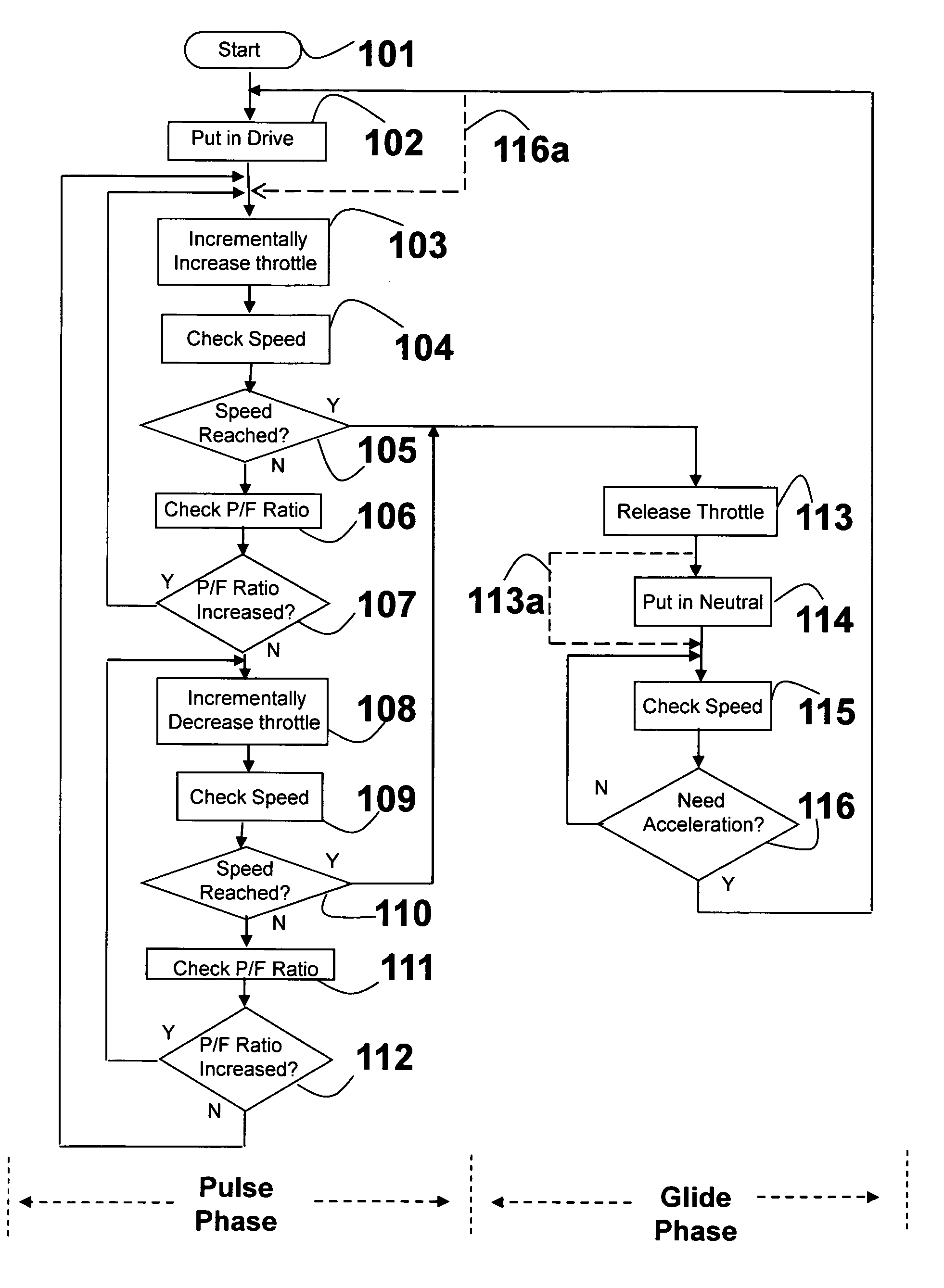
[0042]Embodiment(s) of the present invention are described herein with reference to the drawings. In the drawings, like reference numerals represent like elements. In a most preferred embodiment, a power to fuel ratio is maximized, as explained below.

Maximizing the Power to Fuel Ratio

[0043]A combustion engine converts fuel into power. Generally, the amount of fuel flow to the engine is directly related to how much a driver presses on the accelerator pedal. In other words, the fuel flow rate is linearly proportional to throttle position in typical vehicles (though it need not be).

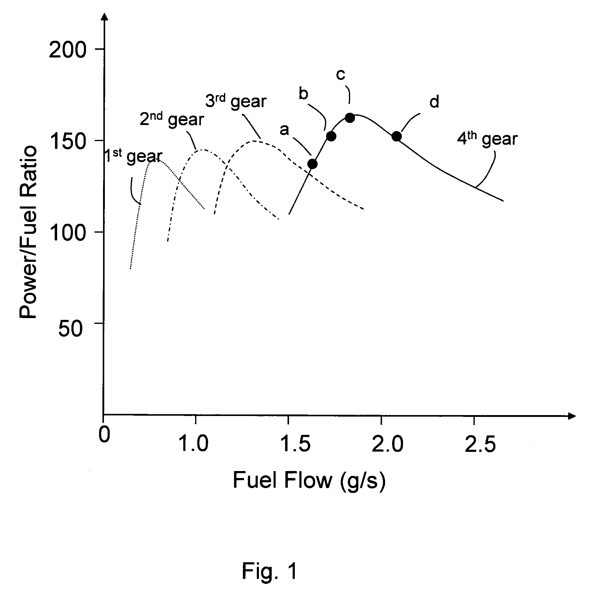
[0044]FIG. 1 shows how a power over fuel ratio (“P / F ratio”) plotted against fuel flow. From FIG. 1, it can readily be seen that the P / F ratio varies with the rate of fuel flow. The P / F ratio is a quantity derived from taking the real-time power produced by the engine (or engine load) and dividing it by the real-time rate of fuel flow (or air flow, which is proportional to fuel flow). The P / F ratio represen...


PUM


Abstract

A system and method for maximizing a vehicle's fuel efficiency preferably without inconveniencing the driver, includes maximizing a ratio of a real-time parameter proportional to engine load or engine power to fuel flow or air flow rate referred to herein as the P/F ratio. This ratio is calculated to evaluate engine fuel efficiency. With the system and method, the throttle is operated incrementally to increase or decrease the throttle in a manner to maximize the P/F ratio, thus maximizing fuel efficiency, in a pulse phase. The system and method implement an on and off pulse width modulation (“PWM”) style of control to modulate engine power and acceleration to achieve the speed that the driver desires, based on the position of the accelerator pedal. When the desired speed is achieved, the throttle is released and when the speed drops a sufficient amount, the throttle is re-engaged to reach the desired speed again. When the throttle is disengaged or when the driver releases the accelerator pedal, the system and method implement a glide phase, where the vehicle coasts without use of fuel or in neutral with very limited use of fuel and minimum engine drag.

Description

CROSS REFERENCE TO RELATED APPLICATION(S)[0001]This application claims priority from U.S. Provisional Patent Application Ser. Nos. 61 / 140,906 filed Dec. 26, 2008; 61 / 184,820, filed Jun. 7, 2009; and 61 / 223,058, filed Jul. 5, 2009, and which all are incorporated by reference herein.BACKGROUND OF THE INVENTION[0002]1. Field of the Invention[0003]The present invention pertains to improving or maximizing fuel efficiency for vehicles that use an internal combustion engine for power.[0004]2. Description of the Related Art[0005]There are many motivations for improving fuel economy of road vehicles (and other vehicles). Transportation represents a significant portion of global energy use. In the United States, for example, the EPA estimates that transportation accounts for approximately twenty five percent of all energy use. Vehicles that consume more fuel emit more greenhouse gases and contribute more significantly to global warming. Given the rapid depletion and increasing scarcity of fos...

Claims


Application Information

Patent Timeline
Patent Type & Authority Patents(United States)
IPC IPC(8): G06F19/00G01F9/02
CPCB60W30/18072B60W30/1882B60W30/143F02D41/0002B60W2030/18081B60W2710/0627F02D2200/0625F02D2200/1002Y02T10/52Y02T10/56Y02T10/42Y02T10/40Y02T10/60Y02T10/84
Inventor HE, JINGHE, HONGPING
Owner HE JING
Why Eureka
Try Eureka