Device for machining ophthalmic lenses, the device having a plurality of machining tools placed on a swivel module

a technology for machining tools and ophthalmic lenses, which is applied in the field of eyeglasses, can solve the problems of inaccurate ophthalmic lens machining, time-consuming maintenance, and high cost and bulky, and achieve the effects of convenient maintenance, improved accuracy, and compact structur

Active Publication Date: 2013-01-01
ESSILOR INT CIE GEN DOPTIQUE
View PDF8 Cites 6 Cited by
  • Summary
  • Abstract
  • Description
  • Claims
  • Application Information

AI Technical Summary

Benefits of technology

[0021]The present invention proposes a novel machining device that is more compact, that is easier to maintain, and that provides improved accuracy, enabling lenses to be drilled close to their support axes and in which at least two tools on distinct axes can be oriented relative to the lens.
[0024]The tools for machining the ophthalmic lens are thus distributed over the machining module, singly or in groups, on distinct axes of rotation. The length of each tool or group of tools is thus short, so that bending forces give rise to little inaccuracy in machining. Furthermore, the overall size of the machining device is reduced. The fact that the machining tools are placed on a swivel-mounted machining module enables these tools to be inclined while they are machining the lens, thereby enabling them to be adapted accurately to the shape and to the configuration of the lens relative to the device. Finally, placing the drill tool on an axis of rotation that is distinct from the axis of the grooving and / or grinding tool enables the drill tool to present an overall diameter that is small. As a result, it can be moved close to the lens support means so as to be able to drill the lens at a very short distance from the support axis of the lens.
[0026]Each machining tool is made of its own material and presents a diameter that is different from the diameters of the other tools, and is adapted to perform machining of a type that differs from the machining of the other tool. The reduction ratio specific to each tool or group of machining tools (which may be greater than or less than 1) enables the speed of rotation of the tool to be adapted to the machining it is to perform. This reduction ratio relative to the speed of the motor also makes it possible to make best use of the power of the motor, and as a result to use a motor of limited power (and therefore inexpensive and compact).
[0028]Consequently, when the machining module pivots about its swivel axis, the end of the drill tool moves over a short stroke, which stroke would be much greater if its axis of rotation were remote from the swivel axis. This short stroke thus enables the end of the drill bit to be positioned quickly relative to the lens. Positioning the drill bit thus requires little space, such that the overall size of the machining device is reduced. Finally, because of this small stroke, the motors serving to place the drill bit facing the lens rotate over a smaller stroke, such that the motors lose fewer steps (loss of reference) and drilling accuracy is increased.
[0031]According to another advantageous characteristic of the invention, the machining module is free to move transversely relative to the blocking axis, and is free to move axially in translation along a transfer axis parallel to said blocking axis relative to the means for supporting the lens and driving it in rotation.

Problems solved by technology

The main drawback of such a machining tool is that the set of wheels comprises numerous tools that are stacked one next to the other so that the set of wheels is cantilevered out over a long length.
While the lens is being machined, bending forces are applied to the set of wheels, thereby deforming it and causing the machining of the ophthalmic lens to become inaccurate.
Furthermore, because of its length, the set of wheels occupies a considerable amount of space and, because of the way the tools are stacked together, it requires time-consuming maintenance.
As a result, it is necessary to use a motor that is powerful, and that is therefore expensive and bulky.
In addition to its high manufacturing cost, such an architecture gives the finishing module size and weight that are considerable.
Finally, only the drill bit can be oriented relative to the lens, which means in particular that it is not possible to modify the orientation of the groove in the edge face of the lens.
Nevertheless, that device does not have a drill tool.
Even assuming it might be envisaged to combine the teaching of the two above-mentioned documents, that would not lead to a device that is fully satisfactory and functional.
Supposing it were envisaged to add an additional tool against the drill of the machining device described in document EP 1 807 244, e.g. a grooving tool, even though no document in the prior art proposes that expressly, there would be remain a problem of providing motor drive for those two tools.
The use of two motors would lead to problems of motorization and of weight.
It would therefore be necessary to use a motor that is powerful and thus expensive and bulky.
In addition, placing those two tools beside each other would lead to interference appearing between the tools and the lens support shafts, which would make it difficult for the drill bit to have access to the central portion of the lens.
Because of such interference, it would then be impossible, or at least difficult, to drill lenses close to their geometrical centers, and that can be problematic with lenses of small dimensions.

Method used


Image

  • Device for machining ophthalmic lenses, the device having a plurality of machining tools placed on a swivel module
  • Device for machining ophthalmic lenses, the device having a plurality of machining tools placed on a swivel module
  • Device for machining ophthalmic lenses, the device having a plurality of machining tools placed on a swivel module

Examples


Embodiment Construction

[0041]The following description with reference to the accompanying drawings given by way of non-limiting example shows clearly what the invention consists in and how it can be reduced to practice.

[0042]In the accompanying drawings:

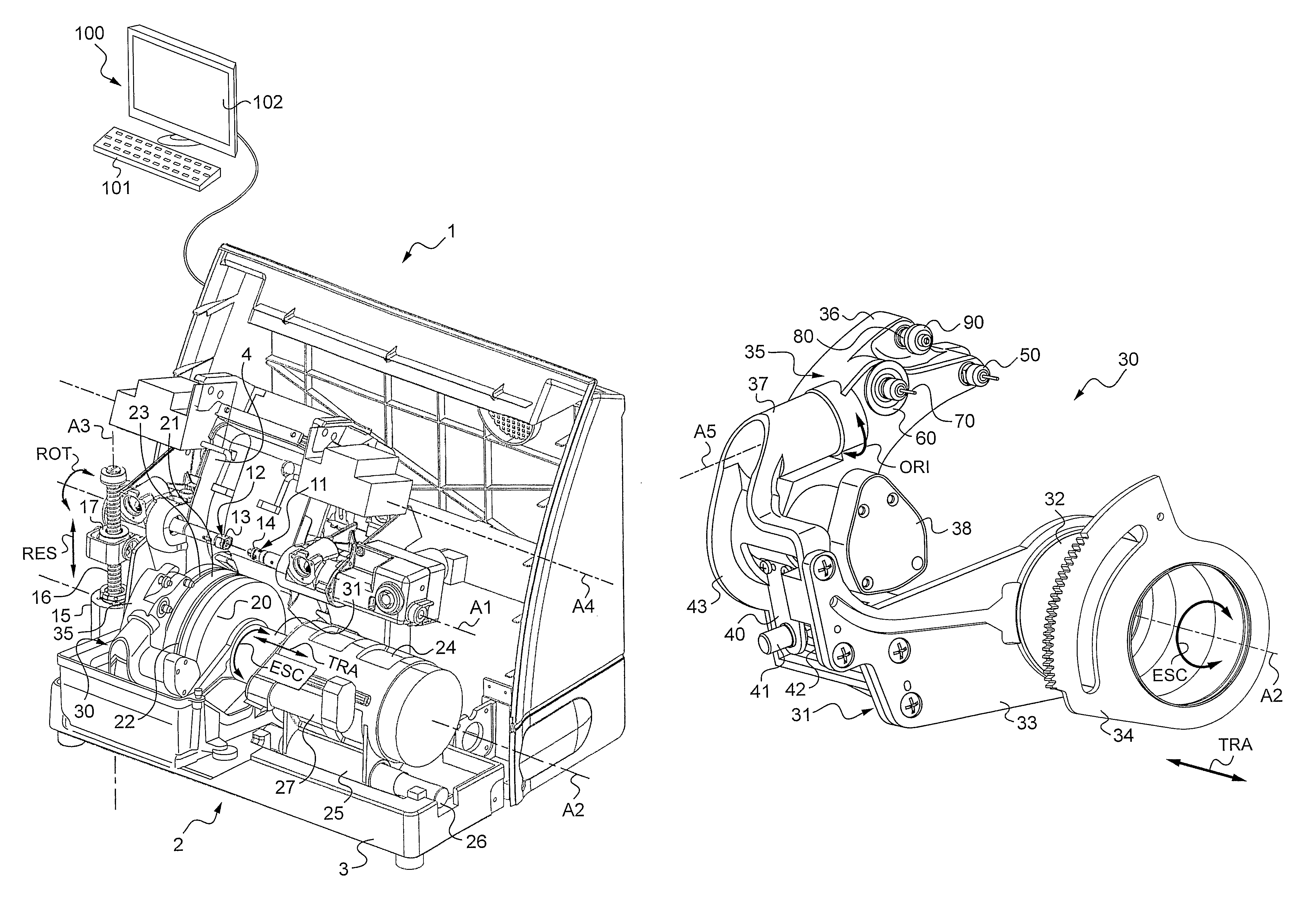
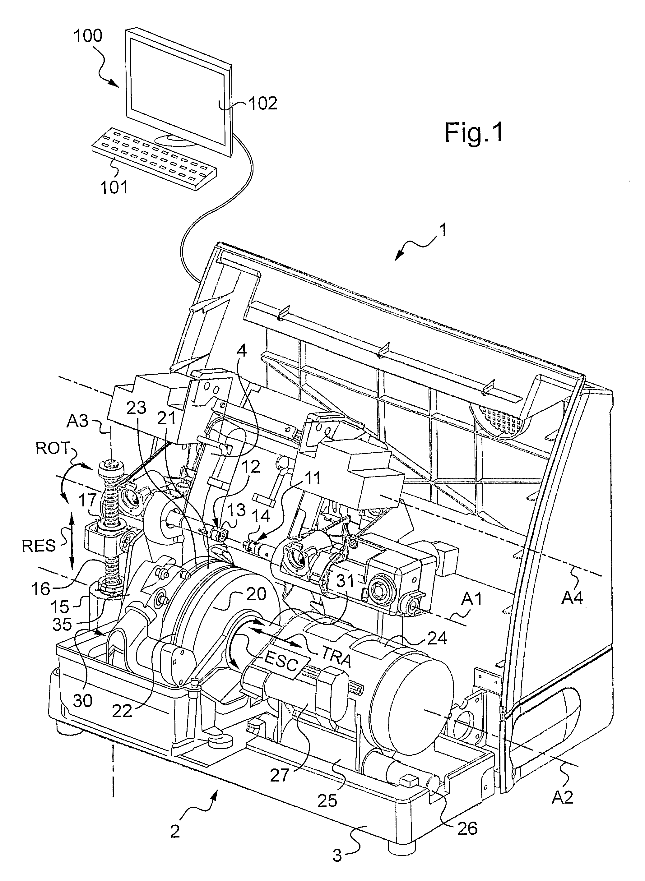
[0043]FIG. 1 is an overall perspective view of a machining device of the invention;

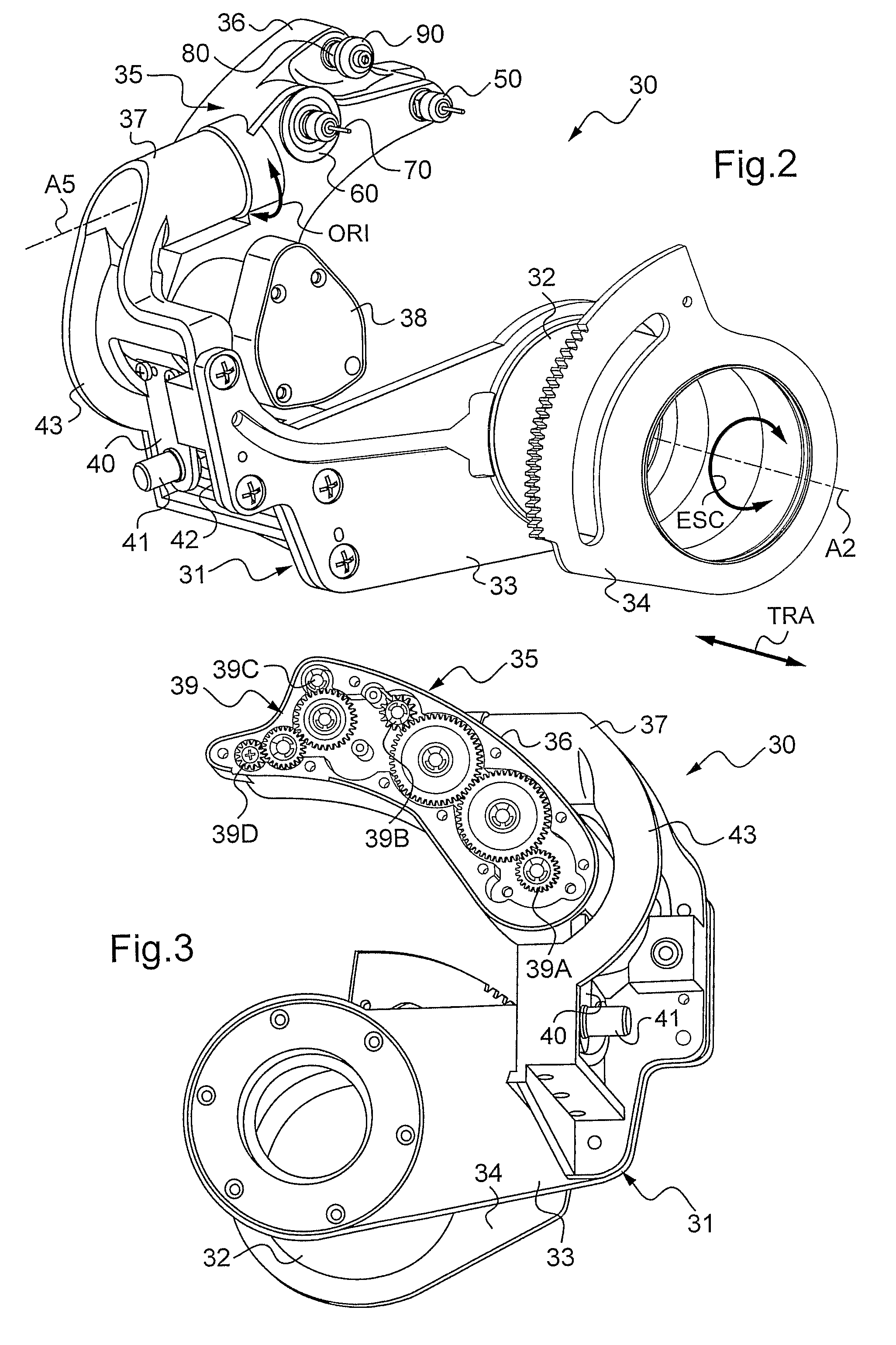
[0044]FIG. 2 is a detail perspective view of a machining arm of the FIG. 1 machining device;

[0045]FIG. 3 is a perspective view of the FIG. 2 machining arm seen from another angle;

[0046]FIG. 4 is a perspective view of the FIG. 2 machining arm including a machining module shown in an inclined position;

[0047]FIG. 5 is a perspective view of the retractable machining arm of FIG. 2 shown from another angle with means for adjusting the orientation of its machining module;

[0048]FIG. 6 is a perspective view of the FIG. 4 machining module seen from another angle;

[0049]FIG. 7 is a plan view of a finishing and polishing module of the machining module of FIG. 4; and

[0050]FIG. 8 is a sect...


PUM

PropertyMeasurementUnit
distanceaaaaaaaaaa
diameteraaaaaaaaaa
degrees of freedomaaaaaaaaaa

Abstract

A device (1) for machining an ophthalmic lens includes a support for the ophthalmic lens and for driving it in rotation about a blocking axis (A1), a machining module (35) that can be swiveled relative to the support and driving the lens in rotation and that is suitable for pivoting about a swivel axis that is not parallel to the blocking axis of the lens, and at least one drill tool mounted to rotate on the machining module about a first axis of rotation. The machining device includes at least one other machining tool mounted to rotate on the machining module about another axis of rotation that is distinct from the first axis of rotation and that is stationary relative to the first axis of rotation.

Description

TECHNICAL FIELD TO WHICH THE INVENTION RELATES[0001]The present invention relates in general to the field of eyeglasses, and more particularly to mounting ophthalmic lenses of a pair of correcting eyeglasses on a frame thereof.[0002]More particularly, the invention relates to a device for machining an ophthalmic lens, the device comprising means for supporting the ophthalmic lens and for driving it in rotation about a blocking axis, a machining module that can be swiveled relative to the means for supporting and driving the lens in rotation and that is suitable for pivoting about a swivel axis that is not parallel to the blocking axis of the lens, and at least one drill tool mounted to rotate on said machining module about a first axis of rotation.TECHNOLOGICAL BACKGROUND[0003]The technical portion of the profession of an optician consists in mounting a pair of ophthalmic lenses in a frame selected by a wearer. Mounting comprises three main operations:[0004]acquiring the shape of th...

Claims


Application Information

Patent Timeline
Patent Type & Authority Patents(United States)
IPC IPC(8): B24B49/00
CPCB24B9/14B24B27/0076B28D1/143Y10T29/5107Y10T29/5114Y10T29/511
Inventor LEMAIRE, CEDRICMICHEL, TONYMAZOYER, GAELMENANT, ANDRE
Owner ESSILOR INT CIE GEN DOPTIQUE
Why Eureka
Try Eureka