Method of controlling an apparatus for generating electric power and apparatus for use in said method

a technology of electric power generation and control apparatus, which is applied in the direction of electrical apparatus, engine control, electrochemical generator, etc., to achieve the effect of constant and/or

Inactive Publication Date: 2013-01-01
BABCOCK & WILCOX VOLUND AS
View PDF13 Cites 4 Cited by
  • Summary
  • Abstract
  • Description
  • Claims
  • Application Information

AI Technical Summary

Benefits of technology

[0007]Based on the above prior art, it is an object of the present invention to provide a simplified method and apparatus of the kind referred to above, by which it is possible to deliver the product gas in controlled amounts directly to the gas engine without the necessity of using a gas holder to compensate for varying production of fuel gas in the updraft gasifier and thus delivering controlled electrical power in accordance with varying requirements, and this is obtained by directly supplying the fuel gas from the gasifier, with suitable cooling and filtering equipment inserted, to the gas engine and by controlling the production of fuel gas in order to maintain a constant and / or controlled electrical output. The control of the fuel gas production can be performed by controlling the amount of gasifying agent supplied to the gasifier.
[0008]Compared to the high-pressure gasifiers, the updraft gasifier, working close to atmospheric pressure, is a much simpler and less costly mechanical device and uses low-cost, low-value biomass materials, such as waste, wood chips, straw, etc. for gasification.

Problems solved by technology

One major disadvantage of the downdraft gasifier is that the produced gas is delivered at a high temperature of approximately 500-650° C., which has to be cooled down immediately in order to reduce explosion risk.
The high-pressure gasifiers are suited for gasifying particulate fossil fuels such as coal or residues from petroleum industry, and produce fuel gas at a high temperature in the range of 500-1000° C. A main disadvantage with such high-pressure gasifiers is that the gasifier confinement has to be a pressure vessel, and that supply of fuel and gasifying agent to the gasifier has to be performed at the high pressure of the gasifier, thus involving use of high-pressure compressors for delivery thereof.

Method used


Image

  • Method of controlling an apparatus for generating electric power and apparatus for use in said method
  • Method of controlling an apparatus for generating electric power and apparatus for use in said method
  • Method of controlling an apparatus for generating electric power and apparatus for use in said method

Examples


Embodiment Construction

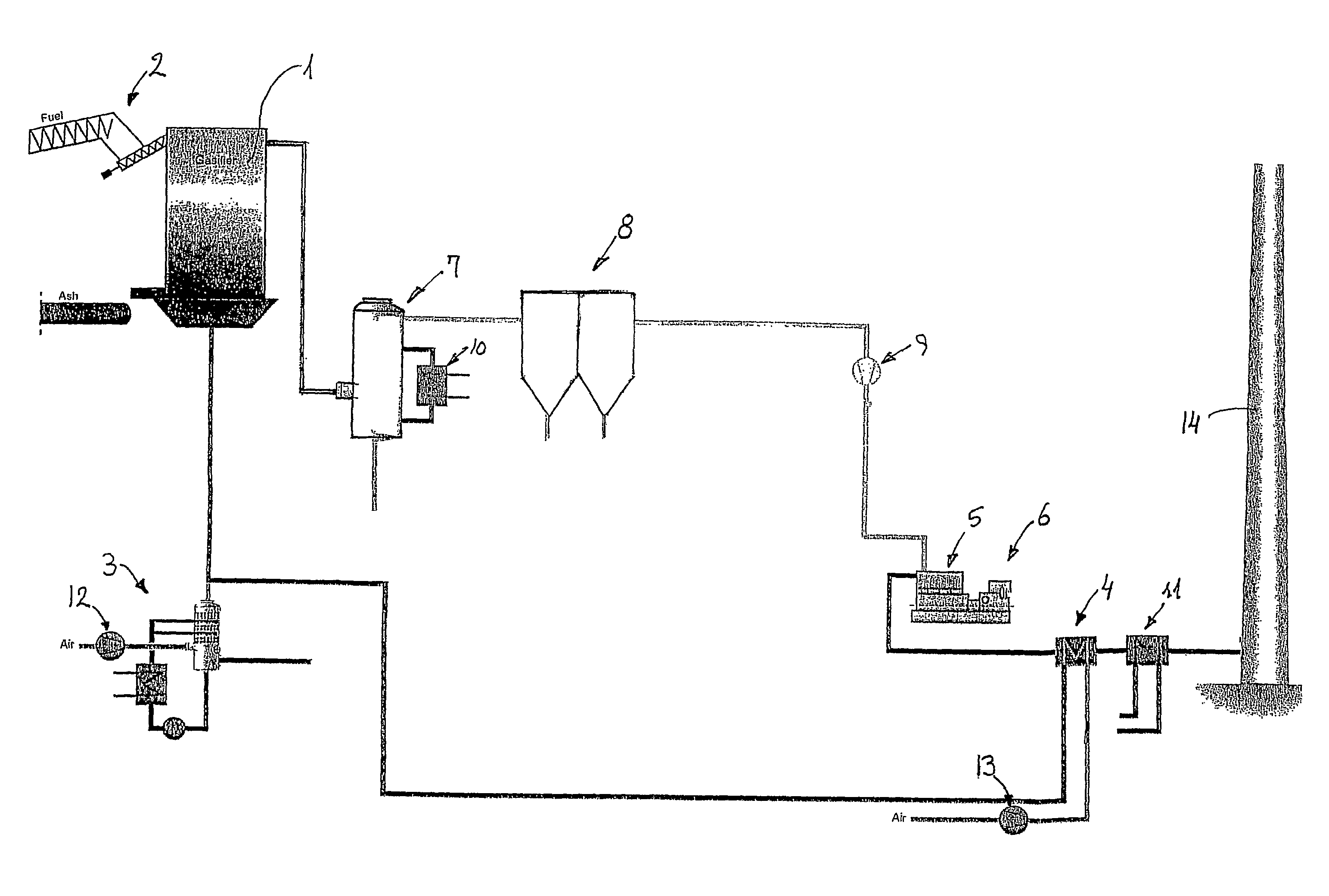
[0014]The apparatus for generating electric power shown in FIG. 1 comprises a gasifier 1 of the shaft and updraft fixed bed type, in which raw material for gasification is charged from the top by means of a charging conveyor 2. Gasifying agent is introduced from the bottom of the gasifier 1 and the gasifying agent comprises humidified and preheated air delivered from a humidifier 3 and a preheater 4. The gas produced in the gasifier 1 is delivered to a gas engine 5 driving a generator 6 for producing electrical power. Gas cleaning equipment in the form of a gas cooling system 7 and an electrostatic precipitator 8 is provided between the gasifier 1 and the gas engine 5 in order to provide a clean gas for the gas engine 5. Furthermore, a fan 9 increases the pressure of the fuel gas delivered to the gas engine 5, said fan 9 being controlled to deliver a constant pressure and being followed by a gas control valve varying the fuel gas flow for this purpose. The gas cooling system 7 is co...


PUM

PropertyMeasurementUnit
temperatureaaaaaaaaaa

Abstract

A method of controlling an apparatus for generating electric power and apparatus for use in said method, the apparatus comprising a gasifier for biomass material, such as waste, wood chips, straw, etc., said gasifier being of the shaft and updraft fixed bed type, which from the top is charged with the raw material for gasification and into the bottom of which gasifying agent is introduced, and a gas engine driving an electrical generator for producing electrical power, said gas engine being driven by the fuel gas from the gasifier. By supplying the produced fuel gas directly from the gasifier to the gas engine and controlling the production of the fuel gas in the gasifier in order to maintain a constant electrical output power, the necessity of using a gas holder between the gasifier and the gas engine is avoided.

Description

TECHNICAL FIELD[0001]The present invention relates to a method of controlling an apparatus for generating electric power and apparatus for use in said method, said apparatus comprising a gasifier for biomass material, such as waste, wood chips, straw, etc., said gasifier being of the shaft and updraft, fixed bed type, which from the top is charged with the raw material for gasification and into the bottom of which gasifying agent is introduced, and a gas engine driving an electrical generator for producing electrical power, said gas engine being driven by the fuel gas produced in the gasifier.BACKGROUND ART[0002]In such apparatus for generating electric power, it is known to use a gas holder between the gasifier and the gas engine or other equipment utilized in the fuel gas produced in order to be able to control the production and use separately and compensate for fluctuations in fuel gas production and thus maintain a constant electrical output power.[0003]From FR 2,844,804 it is ...

Claims


Application Information

Patent Timeline
Patent Type & Authority Patents(United States)
IPC IPC(8): C01B3/36C01B6/24C01B3/24C10J3/00B01J7/00
CPCC10J3/20F02C3/28F02C9/28C10J3/723F05D2270/053C10J2200/158C10J2300/0916C10J2300/0959C10J2300/0973C10J2300/1621C10J2300/165C10J2300/1846C10J2300/1869C10J2300/1876C10J2300/1892Y02E20/14Y02E50/12F05D2270/303F05D2270/301Y02E20/18Y02E50/10Y02P20/129
Inventor GEEST, CLAUSTEISLEV, BJORN
Owner BABCOCK & WILCOX VOLUND AS
Why Eureka
Try Eureka