Turbomachine turbine ring sector

a technology of turbine ring and ring sector, which is applied in the field of turbine ring sector, can solve the problems of reduced service life of the turbine ring, constant gap between prior art documents, and high thermal and mechanical stress, and achieve the effects of reducing the thermal gradient improving the characteristics of the turbine, and increasing the service life of the ring sector

a technology of turbine ring and ring sector, which is applied in the field of turbine ring sector, can solve the problems of reduced service life of the turbine ring, constant gap between prior art documents, and high thermal and mechanical stress, and achieve the effects of reducing the thermal gradient improving the characteristics of the turbine, and increasing the service life of the ring sector

US8348602B2Active Publication Date: 2013-01-08SN DETUDE & DE CONSTR DE MOTEURS DAVIATION S N E C M A

Image

  • Turbomachine turbine ring sector
  • Turbomachine turbine ring sector
  • Turbomachine turbine ring sector

Examples


first embodiment

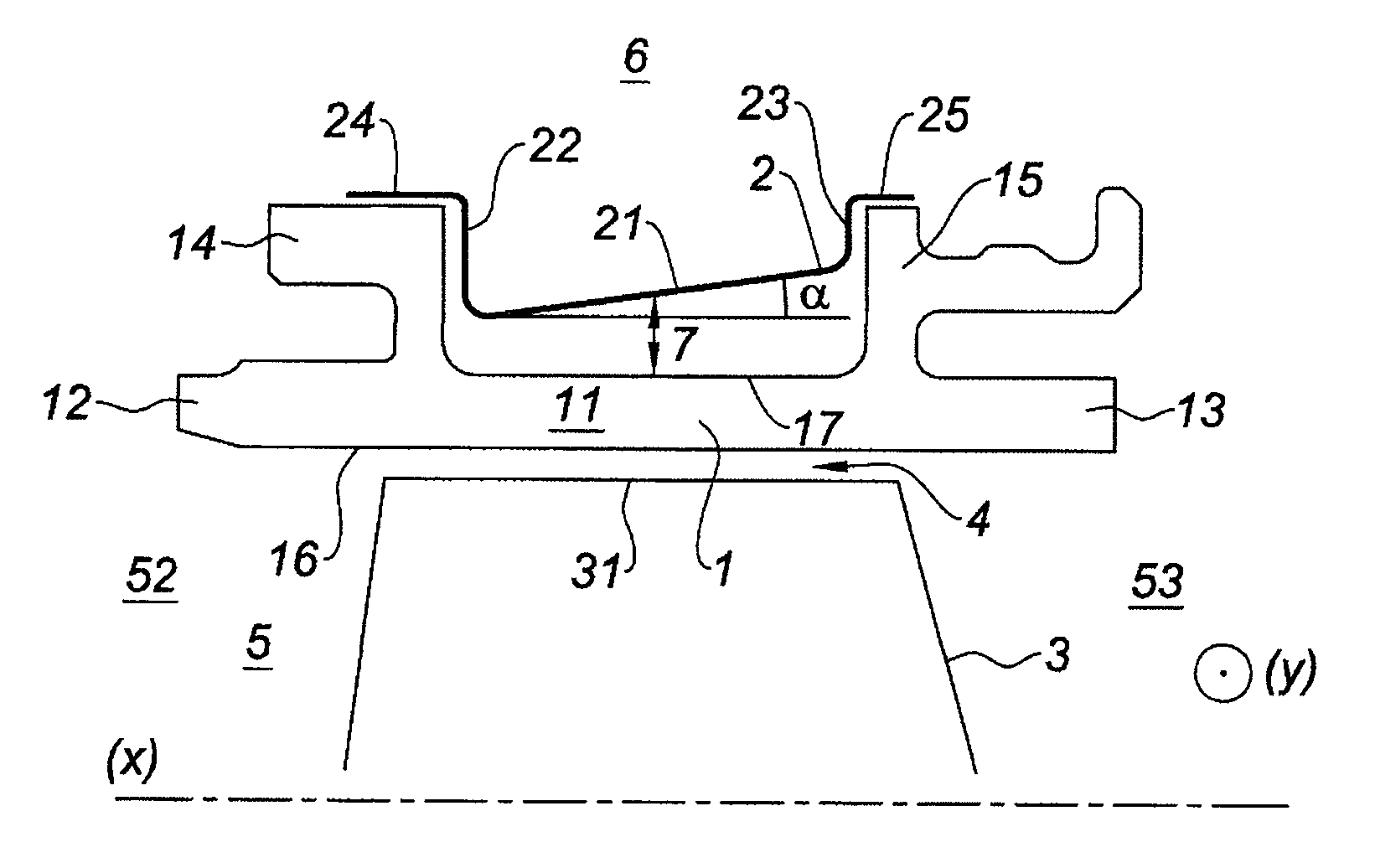
[0038]In the invention represented in FIG. 1, the gap 7 is progressive linearly. The bottom 21 of the multiperforated plate 2 extends in a plane intersecting the axis (X) of revolution of the turbine 8, which is coincident with the axis (X) of revolution of the turbomachine 9. The bottom 21 of the multiperforated plate 2 forms an angle α with the axis (X) of revolution of the turbine 8. This angle α is necessarily greater than 0° and can amount to 45°. According to the operating conditions associated with each turbine, a correctly adjusted slope makes it possible to obtain a more uniform temperature of the ring sector 1.

second embodiment

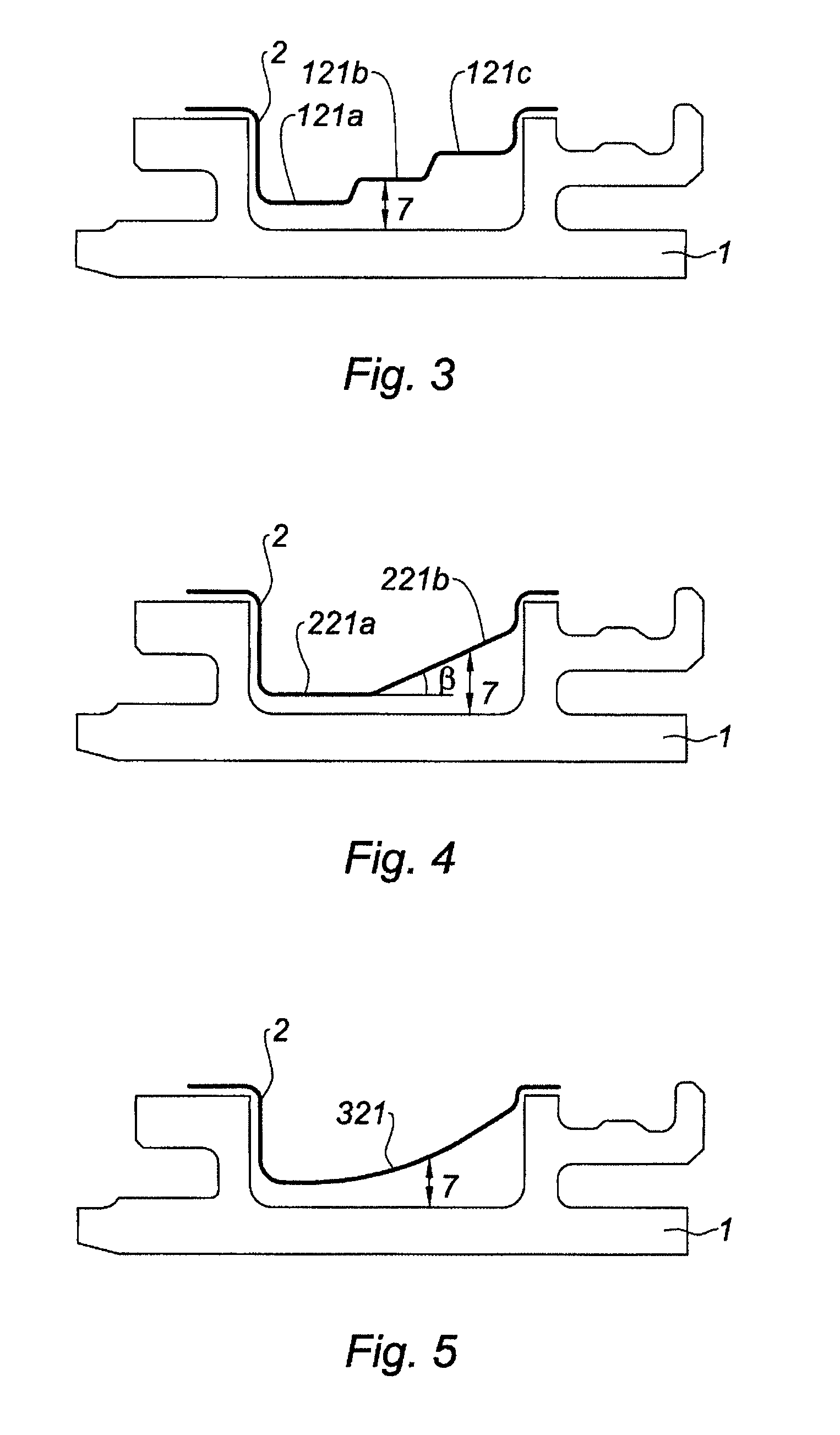
[0039]In the invention represented in FIG. 3, the value of the gap 7 is progressive in stages, the bottom 21 of the multiperforated plate 2 having a “staircase” shape. The bottom 21 of the multiperforated plate 2 consists of a plurality of successive “stages” or “steps”121a, 121b and 121c.

third embodiment

[0040]In the invention represented in FIG. 4, the gap 7 is constant opposite a first part 221a of the multiperforated plate 2 and progressive opposite a second part 221b of the multiperforated plate 2, it being possible for this progression to be linear or curvilinear. In the example illustrated in FIG. 4, the second part 221b progresses linearly and forms an angle β with the first part 221a. This angle β is necessarily greater than 0° and can amount to 60°.


PUM


Abstract

A turbine ring sector is disclosed. The turbine ring sector includes a wall bounding an aerodynamic flowpath in which gases flow from the upstream region toward the downstream region, and a multiperforated plate, situated on the opposite side of the aerodynamic flowpath with respect to the wall. The multiperforated plate includes a bottom and side walls. The distance between the wall of the ring sector and the bottom of the multiperforated plate defines a gap which is progressive in an axial direction, from the upstream region toward the downstream region. The value of the gap situated at the upstream region is below the value of the gap situated at the downstream region.

Description

BACKGROUND OF THE INVENTION AND DESCRIPTION OF THE PRIOR ART[0001]The present invention concerns the field of turbomachines, in particular the cooling of the ring sectors of a turbine of a turbomachine.[0002]An aeronautical turbomachine conventionally includes a compressor, a combustion chamber and a turbine. The job of the turbine is to rotate the compressor by extracting some of the pressure energy from the hot gases leaving the combustion chamber and converting this energy into mechanical energy.[0003]The turbine, situated downstream of the combustion chamber, is the component of the turbomachine that operates under the harshest conditions. It is, in particular, subjected to high thermal and mechanical stresses generated by the hot gases leaving the chamber.[0004]A turbine conventionally comprises at least one nozzle guide vane assembly, consisting of a cascade of vanes which are fixed with respect to the casing of the turbomachine, and at least one rotor, comprising a set of bla...

Claims


Application Information

Patent Timeline
08 Jan 2013
Publication
US8348602B2
IPC
F01D25/14
CPC
F01D11/24; Y02T50/676; F05D2240/11; F05D2250/191; F05D2250/70; F05D2260/201; Y02T50/60
Inventors
BOTREL, ERWAN DANIEL; DORIN, CLAIRE