
Radiation generation device for generating electromagnetic radiation having an adjustable spectral composition, and method of producing same

a radiation generation device and electromagnetic radiation technology, applied in the field of radiation generation devices for generating electromagnetic radiation having an adjustable spectral composition, can solve the problems of increasing overhead for the overall system, affecting the miniaturization of the overall system, and requiring a large amount of effort for the use of several detectors

Active Publication Date: 2013-01-08
FRAUNHOFER GESELLSCHAFT ZUR FOERDERUNG DER ANGEWANDTEN FORSCHUNG EV
View PDF8 Cites 13 Cited by
  • Summary
  • Abstract
  • Description
  • Claims
  • Application Information

AI Technical Summary

Benefits of technology

This solution allows for a compact, cost-effective, and robust light source with adjustable spectral composition, reducing heating and interference issues, and enabling high energy efficiency and miniaturization, suitable for portable and high-resolution spectral analysis applications.

Problems solved by technology

What is disadvantageous in the first possibility is utilization of a movable element, which results in increased overhead for the overall system.
On the other hand, use of an arrangement of several detectors entails a relatively large amount of effort and is relatively expensive, particularly in the infrared wavelength range.
A further disadvantage is the limited miniaturizability of the overall system.
The architecture is comparatively costly and mechanically delicate.
In addition, in this case, too, the radiation source restricts the miniaturization of the overall system on the basis of system integration.
What is disadvantageous is the limitation to specific wavelength ranges with corresponding laser activity, increased effort devoted to the system due to the high levels of mounting accuracy, and the high price resulting therefrom.
Also, when irradiating rough surfaces, the high spatial coherence leads to interference effects, so-called speckles, which may result in measurement errors in the detection.

Method used


Image

  • Radiation generation device for generating electromagnetic radiation having an adjustable spectral composition, and method of producing same
  • Radiation generation device for generating electromagnetic radiation having an adjustable spectral composition, and method of producing same
  • Radiation generation device for generating electromagnetic radiation having an adjustable spectral composition, and method of producing same

Examples


first embodiment

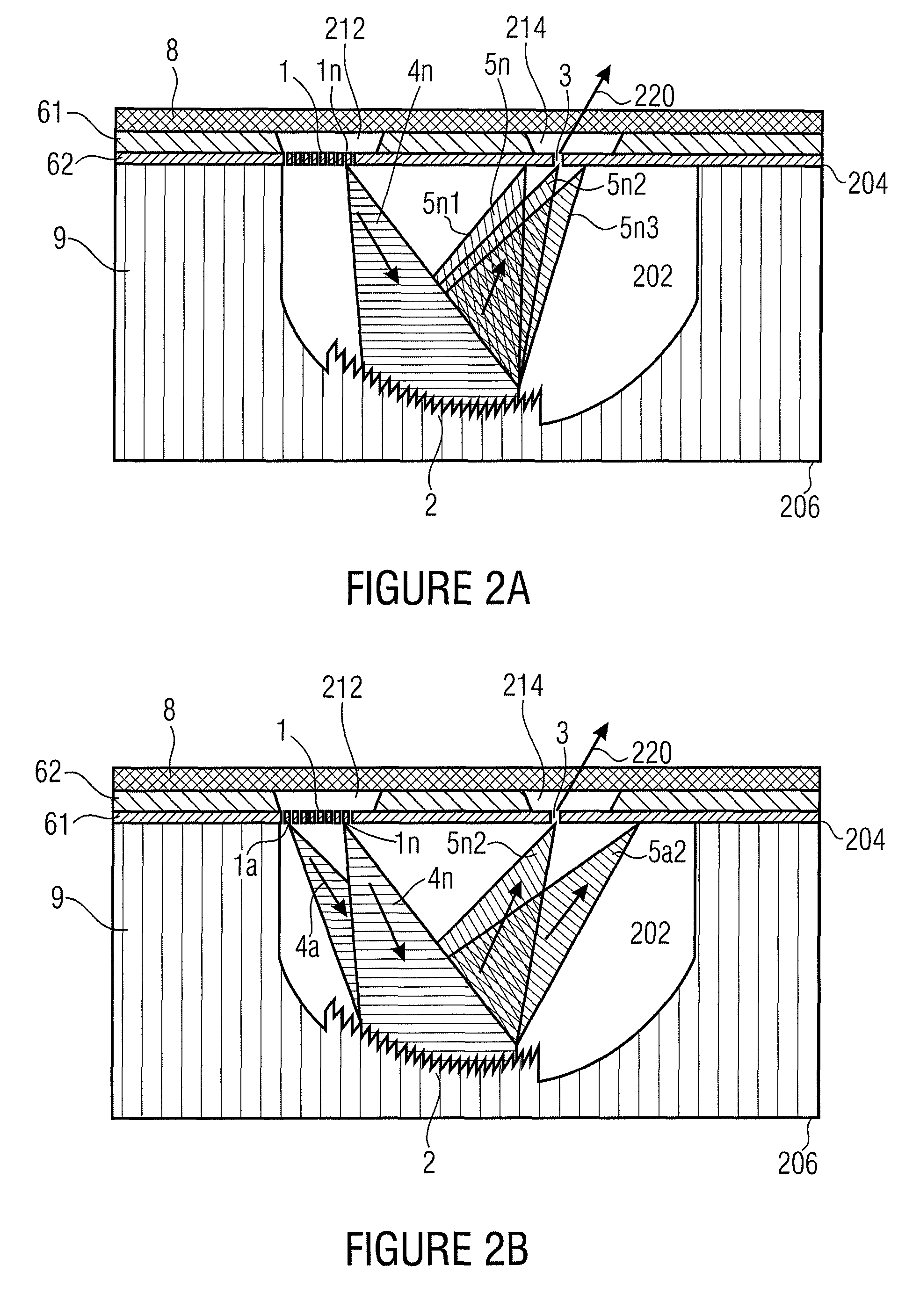
[0047]FIG. 2a shows a schematic cross section of a radiation generation device comprising a first carrier substrate 62, a diaphragm layer or functional layer 61, a second carrier substrate 9, and an encapsulation substrate 8. The second carrier substrate 9 has a first surface 206 and a surface 204 opposite said first surface. The second carrier substrate 9 further has a one-sided recess or cavity 202 that is upwardly opened, in the orientation of FIG. 2a, i.e. that comprises an opening on the side of the second surface 204. The second surface 204 has the functional layer 61 arranged thereon, wherein the radiation elements 1, e.g. the radiation elements 1a to 1n of FIG. 1a, as well as the optical opening 3 are formed. The radiation elements are laterally separated by continuous recesses extending from a first surface of the functional layer, which faces the second carrier substrate 9, to a second surface, opposite the first one, of the functional layer 61, and the optical recess is f...

second embodiment

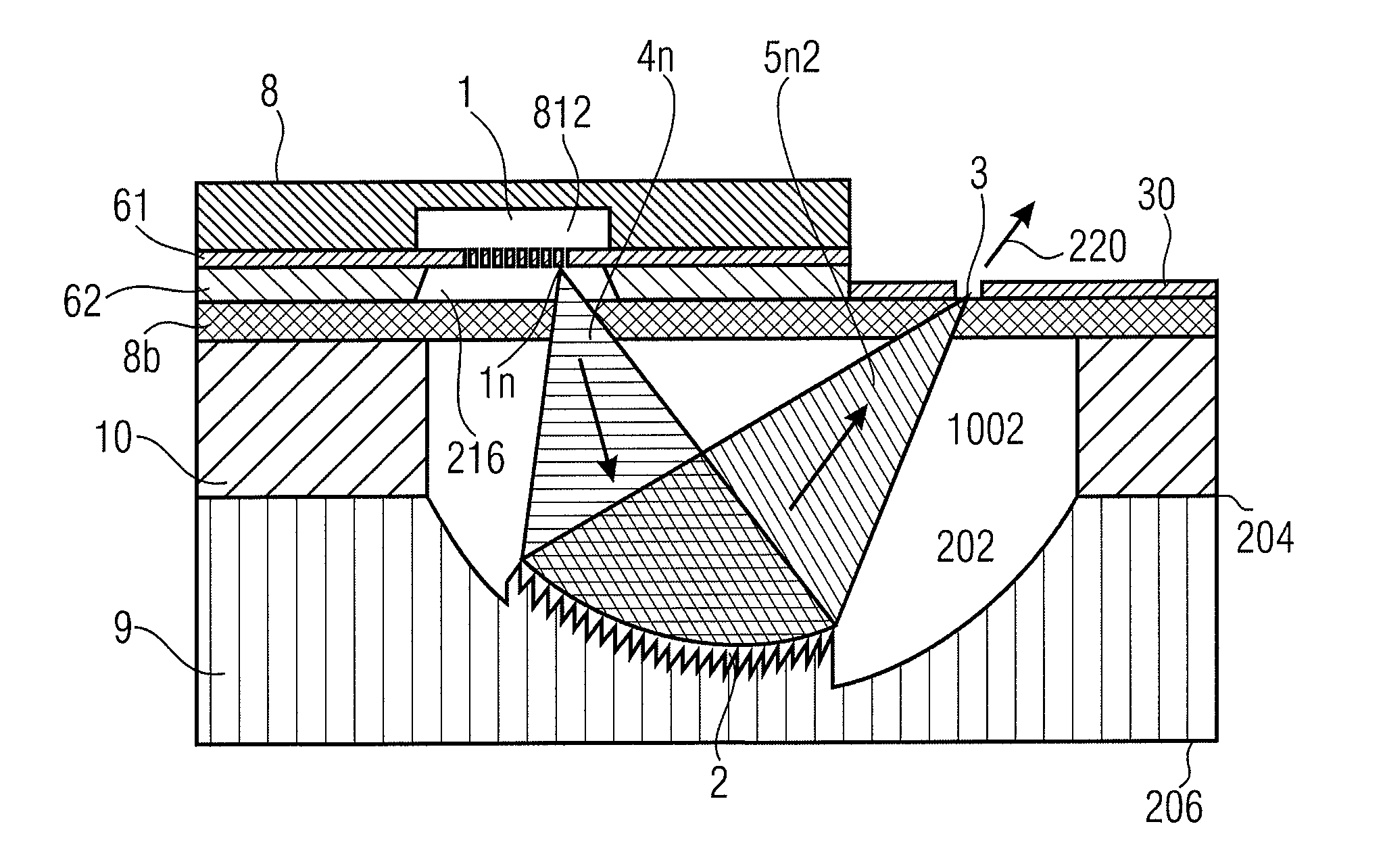
[0066]FIG. 3 shows the radiation generation device, wherein the radiation elements 1 are configured as filaments 1 which, in turn, are arranged in or on an SOI substrate 61, 62. In the embodiment depicted in FIG. 3, the SOI substrate, more specifically the functional layer 62, is encapsulated, on its front side, with a further substrate 8, which is also referred to as an encapsulation substrate 8 and may be a glass substrate, for example. The dispersive optical element 2 used is, again, a concave diffraction grating 2, which is integrated, on the reverse side, into a corresponding second carrier substrate 9. The second carrier substrate 9 may be directly used for front-side encapsulation of the SOI substrate 61, 62. The second carrier substrate 9 is manufactured from a material transparent to electromagnetic radiation, for example from glass or plastic, and, at the same time it serves as the carrier substrate for the opening 3 for coupling out the resulting electromagnetic radiation...

fourth embodiment

[0073]In other words, FIG. 5 generally shows a schematic cross section of a radiation generation device comprising a first carrier substrate 63, radiation elements 1, a second carrier substrate 9, an encapsulation substrate 8, and a non-transparent layer 30. The second carrier substrate 9 has a first surface 206 and a surface 204 opposite said first surface. The second surface 204 of the second carrier substrate has the encapsulation substrate 8 arranged thereon, which comprises a recess 814 arranged below the radiation elements 1.

[0074]The first carrier substrate 63 is arranged above the encapsulation substrate 8, i.e. on the second surface of the encapsulation substrate 8. The radiation elements are arranged on the bottom side of the first carrier substrate 63, i.e. on the first surface of the first carrier substrate 63, which faces the encapsulation substrate 8. The recess 814 of the encapsulation substrate 8 is arranged below the radiation elements and comprises an opening in th...


PUM

PropertyMeasurementUnit
lengthaaaaaaaaaa
lengthaaaaaaaaaa
lengthaaaaaaaaaa

Abstract

A radiation generation device for generating resulting electromagnetic radiation having an adjustable spectral composition includes: a multitude of radiation elements (configured to generate a radiation element specific electromagnetic radiation, respectively, upon being activated, a first radiation element of the multitude of radiation elements being activatable independently of a second radiation element of the multitude of radiation elements; a dispersive optical element; and an optical opening; the dispersive optical element being configured to deflect the radiation element specific electromagnetic radiations, in dependence on their wavelength and on a position of the radiation element generating the respective radiation element specific electromagnetic radiation, such that a particular spectral range of each of the radiation element specific electromagnetic radiations may exit through the optical opening, so that the spectral composition of the resulting electromagnetic radiation exiting through the optical opening is adjustable by selectively activating the multitude of radiation elements.

Description

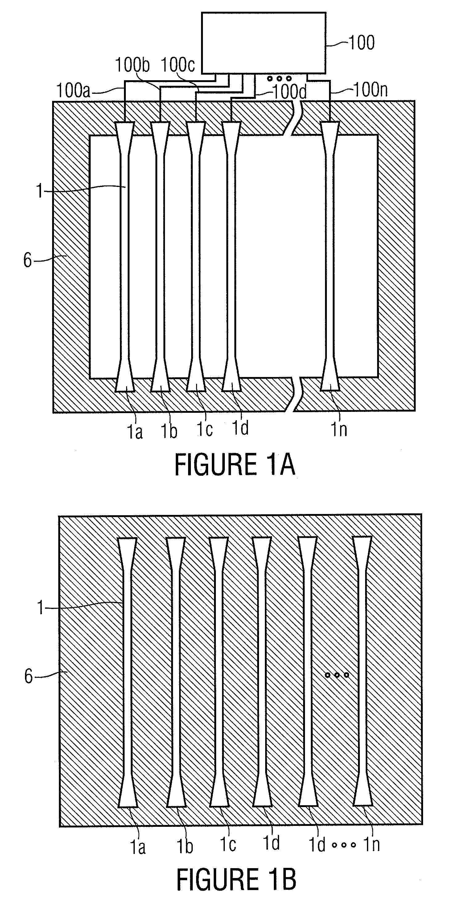
CROSS-REFERENCE TO RELATED APPLICATIONS[0001]This application claims priority from German Patent Application No. 102009046831.5, which was filed on Nov. 18, 2009, and is incorporated herein in its entirety by reference.[0002]The present invention relates to devices for generating electromagnetic radiation having adjustable spectral composition.BACKGROUND OF THE INVENTION[0003]In optical spectral analysis, the composition, the condition or other properties of the object to be examined are examined by means of the interaction of electromagnetic radiation with the surface and at the volume of said object. In this context, the wavelength-dependent reflection, transmission, absorption and scattering properties of materials are exploited.[0004]Various variants of arrangements for performing spectroanalytical examinations have been known.[0005]A first variant illuminates the sample with the entire polychrome spectrum of a light source, for example a halogen lamp or a thermal radiator. The ...

Claims


Application Information

Patent Timeline
Patent Type & Authority Patents(United States)
IPC IPC(8): G01J3/28
CPCG01J3/0256G01J3/10G01J3/18Y10T29/49826G01J2003/1282G01J2003/1286G01J2003/106G01J3/0208G01J3/14
Inventor GRUEGER, HEINRICHKNOBBE, JENSEGLOFF, THOMASMUELLER, MICHAEL
Owner FRAUNHOFER GESELLSCHAFT ZUR FOERDERUNG DER ANGEWANDTEN FORSCHUNG EV
Learn More