

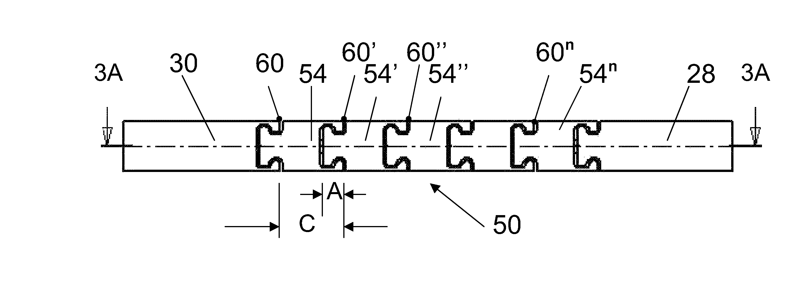
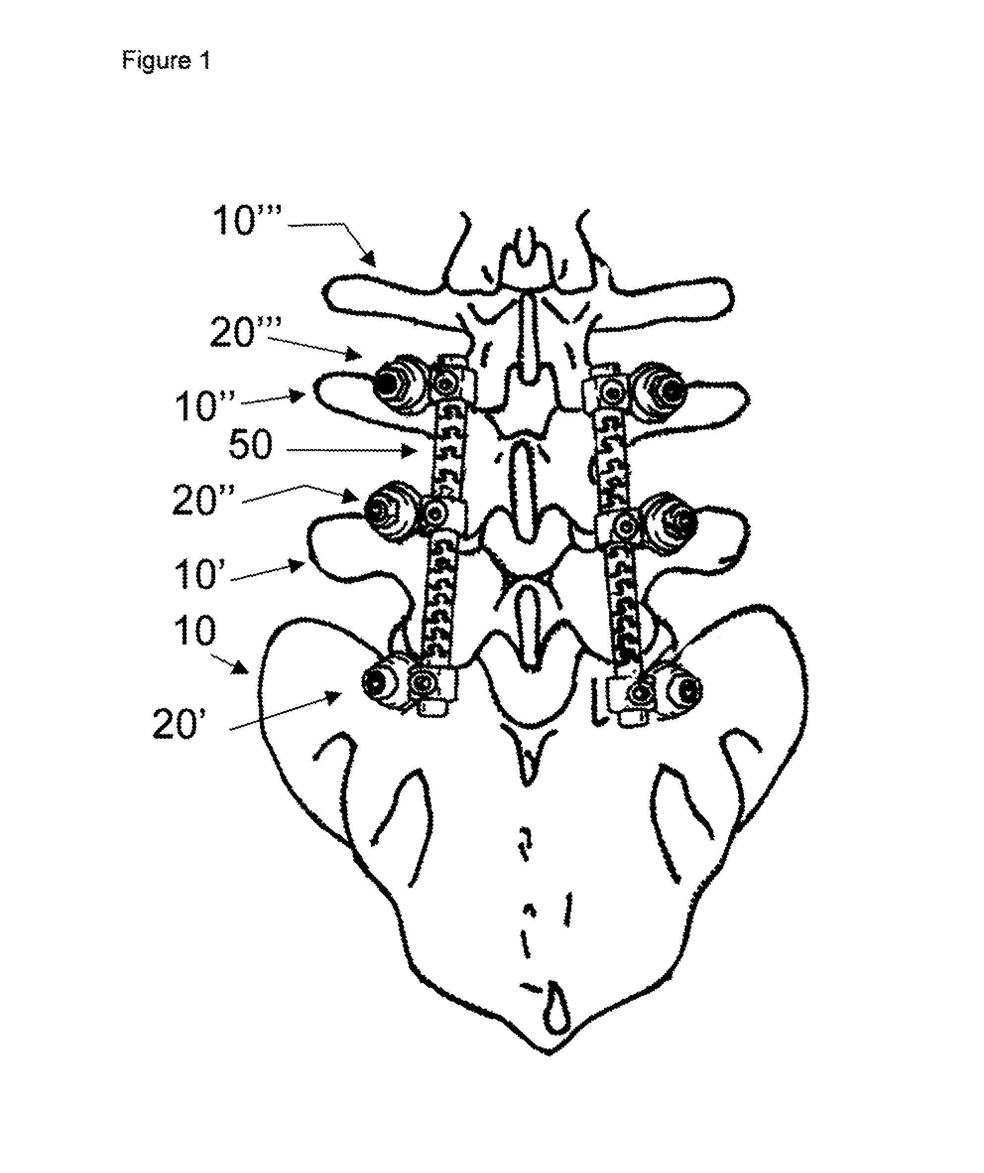
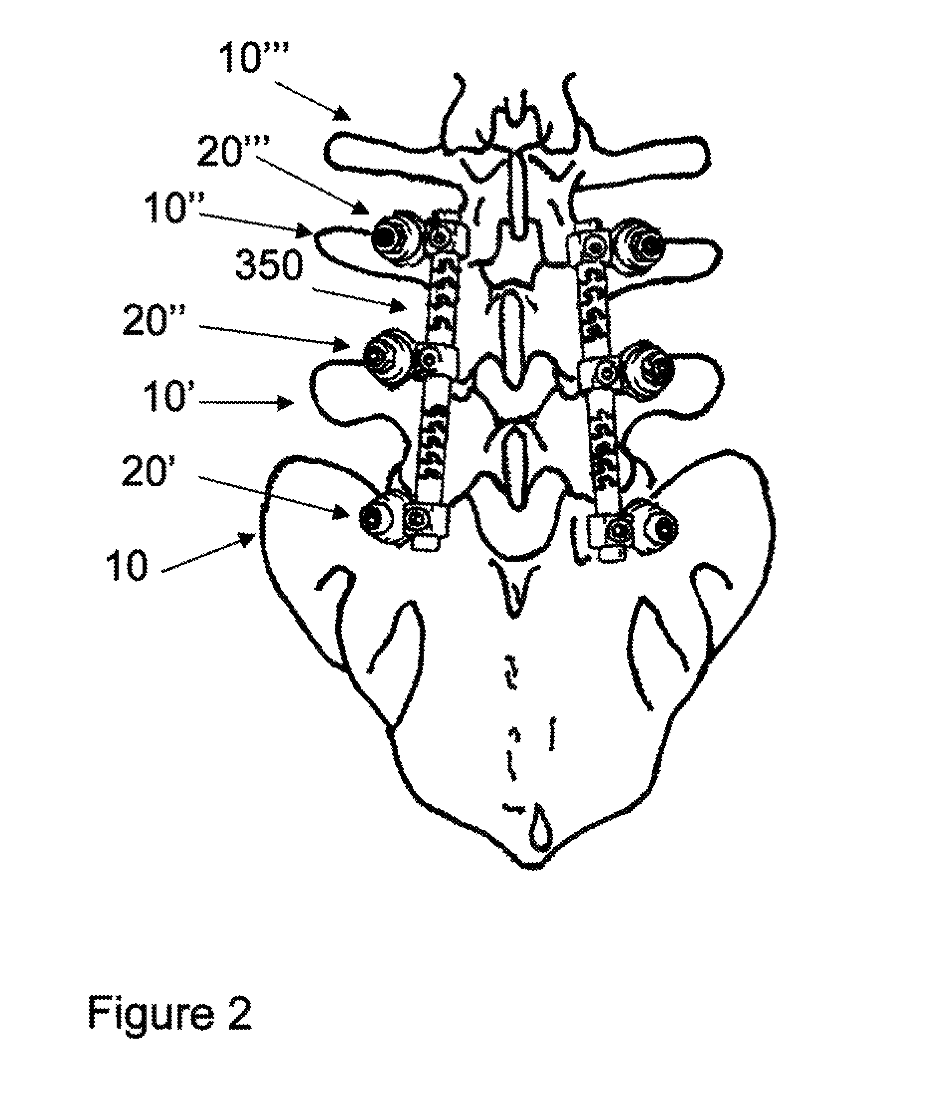
Flexible spine components having a concentric slot
a flexible and concentric technology, applied in the field of flexible rod connectors, can solve the problems of increasing the chance of implant failure or improper insertion, frequent in vivo failure of rigid structures, and extreme limitation of flexion and torsional movements, so as to increase the flexibility of components, reduce the chance of improper insertion, and ensure the effect of flexion and torsional movemen
- Summary
- Abstract
- Description
- Claims
- Application Information
AI Technical Summary
Benefits of technology
Problems solved by technology
Method used
Image

Examples
Embodiment Construction
Definitions and Terms
[0049]The term slot as used herein, is defined in the American Heritage Dictionary, 3rd Edition, Copyright 1994, as follows:
[0050]For the purposes herein the terms “slit” and “slot” are used interchangeably, consistent with their definitions, as follows:
[0051]slot n. 1. A narrow opening; a groove or slit: a slot for coins in a vending machine; a mail slot.
[0052]2. A gap between a main and an auxiliary airfoil to provide space for airflow and facilitate the smooth passage of air over the wing.
[0053]For the purposes herein the term pitch as used herein is defined as:
[0054]pitch—n.1. The distance traveled by a machine screw in one revolution.
[0055]2. The distance between two corresponding points on adjacent screw threads or gear teeth.
[0056]For the purposes herein the term “cycle” shall refer to:
[0057]Cycle—1. An interval of time during which a characteristic, often regularly repeated event or sequence of events occurs: Sunspots increase and decrease in intensity i...
PUM
 Abstract
Description
Claims
Application Information