Hybrid optical-electrical probes for stimulation of nerve or other animal tissue

a technology of optical-electrical probes and nerves, applied in the field of tissue optics, can solve the problems of affecting the ability to walk or keep balance, people lose vestibular hair cells, and suffer from balance and dizziness problems, and achieve the effects of excellent conductor, simple operation, and enhanced functionality

Inactive Publication Date: 2013-01-22
LOCKHEED MARTIN ACULIGHT CORP
View PDF207 Cites 14 Cited by
  • Summary
  • Abstract
  • Description
  • Claims
  • Application Information

AI Technical Summary

Benefits of technology

[0021]In some embodiments, the probe is attached to an implanted device (such as a battery-powered microprocessor-controlled device that transmits an optical signal to stimulate a portion of an animal (such as the vestibular nerves of a human, for example; however, the invention is not limited to the vestibular system, but rather is generally useful for any use that benefits from both optical and electrical signals to and from one or more tissues of an animal) and that electrically senses a biological response (such as a compound nerve-action potential (CNAP) response of a stimulated nerve)) or a physical condition (such as the temperature at the probe end, in order to determine the amount of heating resulting from the optical stimulation, so as to deliver an amount of light that is effective to obtain the nerve stimulation response without overheating and damaging tissue). In some embodiments, the sensed response or condition is used to control (e.g., increase, decrease, start, or stop) the optical signal in order to obtain better treatment effectiveness and more precise control of the desired response. In some embodiments, the optical fiber is also or instead used to deliver a much more intense light pulse or series of pulses, in order to provide therapy-type or surgery-type results, such as ablating unwanted tissue, wherein there is an interaction between the intense light pulses that is sensed by received electrical signals conducted from the fiber tip along the electrical conductors on the optical fiber, and / or enhanced by electrical signals that are delivered to the fiber tip along the electrical conductors on the optical fiber.
[0024]In some embodiments, the device of the present invention is used in the stimulation of the vestibular system. It is often necessary, during the placement of probes (e.g., optical fibers), to be able to both stimulate and detect the response resulting from the stimulation of the vestibular system. Being able to have a single probe that does this facilitates this placement process.
[0029]In some embodiments, the present invention is used in applications where there is a need for precise placement of an electrode, but with the requirement to stimulate a large number of nerves, either simultaneously or individually. A single-core optical element (e.g., a fiber with a single waveguide) allows for extremely precise stimulation but can lack the ability to supply and / or spread enough power to stimulate large areas of nerves. In some embodiments, the electrical portion of the probe lacks specificity (since even with a point source of electricity, the electrical signal will spread across electrically conductive tissue), but can provide sufficient power to stimulate large areas. In some embodiments, the optical-electrical probe of the present invention is used in deep brain stimulation where locating the probe at the interface between the thalamus and hypothalamus is important, but once there, a relatively large area of the brain needs to be stimulated.
[0031]The present invention provides several approaches to doing this. One uses discrete electrical probes located immediately adjacent to the optical fiber. The fiber and electrodes can be held together in a cannula, glass tube, polyimide sleeve or any other biocompatible material. This has the advantage of being very simple to do and allows independent optimization of the optical fiber and electrical probes.
[0032]A more compact approach, used in some embodiments, actually uses the fiber to carry both the optical and electrical signals. It is well known how to put metallized coatings on optical fibers. It is done routinely in order to be able to attach the fiber to optical mounts using solder for the purpose of alignment. In some embodiments, the metal-layer structure includes typically a combination of Ni (for adhesion to the fiber), Pt, and / or Au (for wetability to the solder). In the present invention, the Au layer provides an excellent conductor for the electrical signal. Several configurations of the conductor(s) on an optical fiber are shown in the attached figures. The simplest monopolar configuration will be adequate for many applications. However, the multi-electrode configurations can provide additional functionality as well as spatial selectivity.
[0033]Other embodiments use a configuration where the fiber is slid into a sleeve or jacket (or wrapped with a spirally wound film having one or more length-wise metallized conductors that when wound forms such a sleeve) that is patterned with the electrodes (e.g., a Kapton or other flex circuit, wherein metal conductors are formed and patterned (e.g., as parallel conductors extending along its length) on a polymer substrate (and optionally covered with another polymer, glass, silicon nitride or the like as a top insulator), and this substrate with its conductors is wound or wrapped on the optical fiber). This allows independent fabrication of more complex electrode patterns without having to develop new processes for metallizing the fibers. The Kapton-substrate circuits also readily lend themselves to easy termination. Any flexible substrate that can support a metal pattern and is biocompatible can be used for this configuration.

Problems solved by technology

Some people lose vestibular hair cells or suffer from balance and dizziness problems that are not readily treatable through therapy and / or drugs.
These conditions can be very debilitating, since the affected person must remain still to minimize unpleasant dizziness or feeling continuously “seasick.” The condition can also affect their ability to walk or keep their balance in general.
Damage to the otoliths or their central connections can impair ocular and body stabilization.

Method used


Image

  • Hybrid optical-electrical probes for stimulation of nerve or other animal tissue
  • Hybrid optical-electrical probes for stimulation of nerve or other animal tissue
  • Hybrid optical-electrical probes for stimulation of nerve or other animal tissue

Examples


embodiment 202

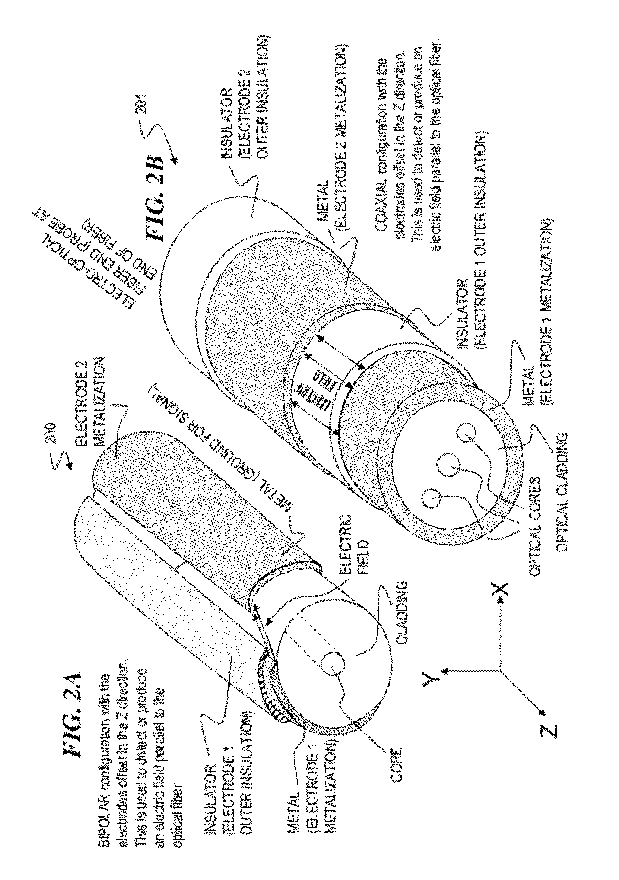
[0065]FIG. 2C is a perspective view of an embodiment 202 of the invention in which coaxial metallic coatings of an optical fiber functions in an electrode capacity, in a bipolar configuration with the electrodes offset, relative to one another, in the Z direction, and in which a coaxial film outer conductive layer forms an electromagnetic shield for the signals carried on the inner conductive layers.

[0066]FIG. 2D shows a cross-section view of an optical fiber 203 having a split two-part / bipolar co-axial metal electrical conductor deposited on the optical fiber and a coaxial film outer conductive layer shield deposited on an insulator that covers the two-part electrical conductor.

embodiment 301

[0067]FIG. 3A shows a perspective view of an embodiment 301 of the invention in which an optical fiber is co-located with a separate, monopolar electrode, within a sheathing or a cannula.

embodiment 302

[0068]FIG. 3B shows a perspective view of an embodiment 302 of the invention in which an optical fiber is co-located with a separate, bipolar electrode.


PUM


Abstract

An optical-signal vestibular-nerve stimulation device and method that provides different nerve stimulation signals to a plurality of different vestibular nerves, including at least some of the three semicircular canal nerves and the two otolith organ nerves. In some embodiments, balance conditions of the person are sensed by the implanted device, and based on the sensed balance conditions, varying infrared (IR) nerve-stimulation signals are sent to a plurality of the different vestibular nerves.

Description

CROSS-REFERENCE TO RELATED APPLICATIONS[0001]This is a divisional of and claims benefit of U.S. patent application Ser. No. 12 / 018,185 filed Jan. 22, 2008 (which issued as U.S. Pat. No. 7,883,536 on Feb. 8, 2011), titled “HYBRID OPTICAL-ELECTRICAL PROBES,” which claims benefit ofU.S. Provisional Patent Application No. 60 / 885,879 filed Jan. 19, 2007, titled “Hybrid Optical-Electrical Probes”; andU.S. Provisional Patent Application No. 60 / 964,634 filed Aug. 13, 2007, titled “VCSEL Array Stimulator Apparatus and Method for Light Stimulation of Bodily Tissues”;each of which is incorporated herein by reference in its entirety.[0002]This invention is also related to priorU.S. patent application Ser. No. 11 / 257,793 filed Oct. 24, 2005 (which issued as U.S. Pat. No. 7,736,382 on Jun. 15, 2010), titled “Apparatus and Method for Optical Stimulation of Nerves and Other Animal Tissue”;U.S. patent application Ser. No. 11 / 536,639 filed Sep. 28, 2006, titled “Miniature Apparatus and Method for Opt...

Claims


Application Information

Patent Timeline
Patent Type & Authority Patents(United States)
IPC IPC(8): A61N1/05
CPCA61N5/0603A61N5/0622A61N2005/0605A61N2005/063A61N2005/0647A61N2005/0659
Inventor BENDETT, MARK P.WEBB, JAMES S.
Owner LOCKHEED MARTIN ACULIGHT CORP
Why Eureka
Try Eureka