Handlebar switch assembly

a technology for hand-held switches and assemblies, which is applied in the direction of steering devices, cycle equipments, optical signals, etc., can solve the problem that the pushing surface is too far from the thumb to easily operate the switch,

Active Publication Date: 2013-01-22
HONDA MOTOR CO LTD
View PDF9 Cites 12 Cited by
  • Summary
  • Abstract
  • Description
  • Claims
  • Application Information

AI Technical Summary

Benefits of technology

[0006]An object of an embodiment of the present invention is to address the above problem of the above related art and provide a handlebar switch assembly in which the operability of a shift-up switch and a shift-down switch, both separately provided on a switch case, is enhanced.

Problems solved by technology

On the other hand, as for the shift-down switch, its pushing part is located in a more forward position of the vehicle than the axis line of the handlebar, protruding below the switch case, so there is a problem that the pushing surface is too remote from the thumb to operate it easily.

Method used


Image

  • Handlebar switch assembly
  • Handlebar switch assembly
  • Handlebar switch assembly

Examples


first embodiment

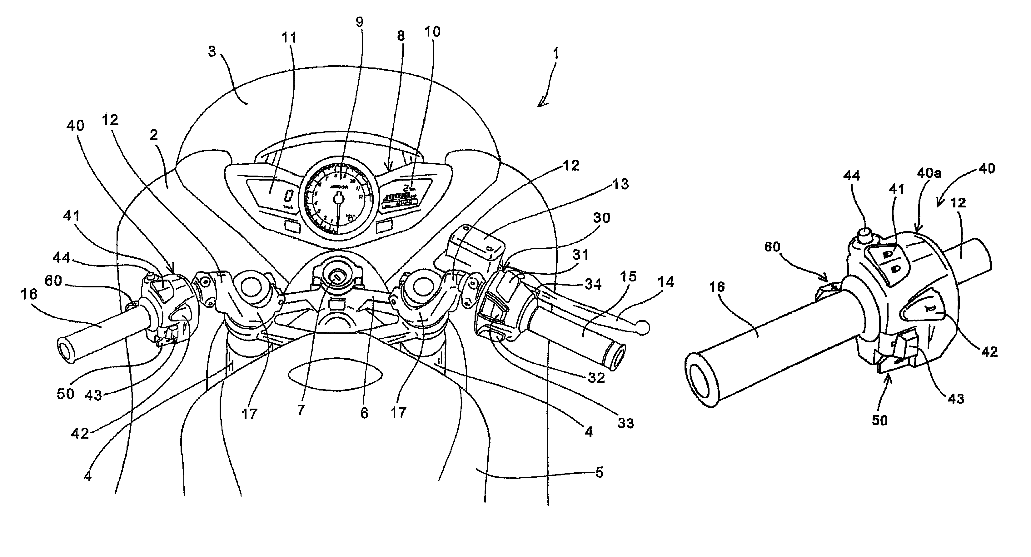
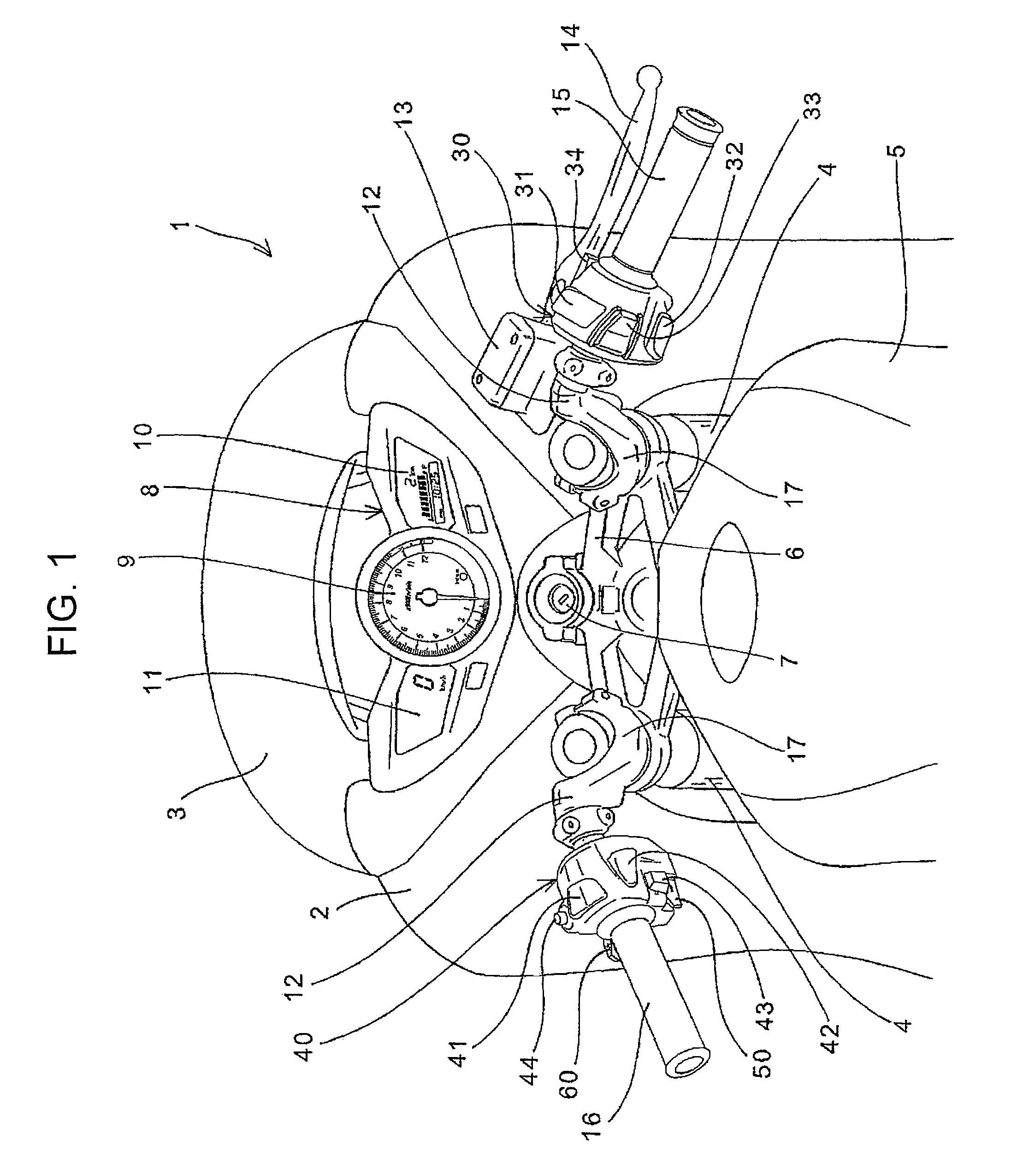
[0062]Preferred embodiments of the invention will be described in detail referring to drawings. FIG. 1 is a fragmentary enlarged view of a motorcycle 1 to which a handlebar switch assembly according to the invention is applied. FIG. 1 illustrates a handlebar and its vicinity as looked down from behind and above the vehicle body and illustrates almost the same as what an occupant (rider) seated on the seat sees.

[0063]The vehicle front side of a pair of left and right handlebars 12 for steering a front wheel (not shown) is covered by a cowling 2 as an exterior component. A transparent or translucent windbreak screen 3 is attached to the center top of the cowling 2 and located below the screen is a meter unit 8 having a liquid crystal panel 10 which can show a tachometer 9, a speed meter 11, a fuel gauge, a clock and so on.

[0064]The front wheel of the motorcycle 1 is rotatably journalled to the lower ends of a pair of left and right front forks 4 and the upper parts of the front forks ...

second embodiment

[0101]FIG. 13 is a fragmentary enlarged view of a motorcycle 1 to which a handlebar switch assembly according to the invention is applied. Since the only differences from FIG. 1 are left and right handlebar switch assemblies, descriptions of the other common parts will be omitted. Handlebar switch assemblies 200 and 300 having operation switches for various electric parts are fitted to the left and right handlebars 12 adjacently to the vehicle center side of the handlebar grips 15 and 16. The left handlebar switch assembly 200 has a headlight optical axis changeover switch 204, a horn switch 205, a turn signal switch 207, a hazard lamp switch 203, and a shift-down switch 208 and a shift-up switch 206 for automatic transmission gear shift. On the other hand, the right handlebar switch assembly 300 has an engine stop switch 304, a neutral / drive changeover switch 305, a starter switch 306 and a run mode changeover switch 303.

[0102]FIG. 14 is a front view of the left handlebar switch as...


PUM


Abstract

A handlebar switch assembly for enhancing operability of a shift-up switch and a shift-down switch separately provided on a switch case. Viewing a switch case from an axis line direction of a handlebar, four zones are defined with the axis line, a rear upper zone and a rear lower zone, both located opposite to an occupant, and a front upper zone and a front lower zone, both located on the vehicle front side. A first shift switch and a second shift switch are swing-type switches in which operating elements swing when a pushing force is applied. The shift-up switch is located in the front lower zone so as to orient one end of its operating element outward in the vehicle transverse direction and the shift-down switch is located in the rear lower zone so as to orient one end of its operating element outward in the vehicle transverse direction.

Description

CROSS-REFERENCE TO RELATED APPLICATIONS[0001]The present application claims priority under 35 USC 119 to Japanese Patent Application Nos. 2009-109140 filed on Apr. 28, 2009 and 2009-214403 filed on Sep. 16, 2009 the entire contents of which are hereby incorporated by reference.FIELD OF THE INVENTION[0002]The present invention relates to handlebar switch assemblies and more particularly to a handlebar switch assembly in which a shift switch for transmission gear shift is provided on a switch case adjacent to a handlebar grip.DESCRIPTION OF BACKGROUND ART[0003]A handlebar switch assembly is known wherein a shift-up switch and a shift-down switch for a transmission gear shift are separately provided on a switch case fitted to the handlebar of a motorcycle.[0004]Japanese Patent No. 4166474 discloses a handlebar switch assembly in which a shift-up switch journalled to a swing shaft oriented along the vertical direction of the vehicle is located on the vehicle front side of a switch case ...

Claims


Application Information

Patent Timeline
Patent Type & Authority Patents(United States)
IPC IPC(8): H01H9/06
CPCB60K20/06B62K11/14B62K23/02H01H9/06B60Y2200/12H01H2009/068B60K20/02B62J6/16B62K21/12
Inventor MURASAWA, NAOKINAKAHIRA, KOTAICHIKAWA, MANABU
Owner HONDA MOTOR CO LTD
Why Eureka
Try Eureka