Arrangement having an electric machine and method for operating an electric machine

a technology of electric machines and electrical machines, applied in the direction of dynamo-electric converter control, motor/generator/converter stoppers, optical radiation measurement, etc., can solve the problems of difficult operation, inability to measure the temperature of rotating parts in practice, and inability to use contact thermometers. , to achieve the effect of not increasing the total diameter of the electrical machine, good thermal conductivity and low thermal thickness

Inactive Publication Date: 2013-01-22
SIEMENS AG
View PDF13 Cites 3 Cited by
  • Summary
  • Abstract
  • Description
  • Claims
  • Application Information

AI Technical Summary

Benefits of technology

[0014]It is particularly advantageous to integrate the infrared temperature sensor, and therefore the thermopile, in a slot sealing wedge of a slot in the stator of an electrical machine. As a result, there is no need to structurally provide further installation space for the thermal sensor. In particular, the total diameter of the electrical machine is not increased or is not substantially increased as a result. A further advantage is that the connection lines of the infrared temperature sensor in the installation space between the stator winding and the slot sealing wedge can be axially routed out of the stator. In this case, it is particularly advantageous for the intrinsic temperature measurement (also called the “measurement at a point of comparison”) of the thermopiles themselves to be simultaneously used to detect the (local) temperature of the stator or of the stator winding of the respective phase in question, as a result of which no additional hardware is required for detecting the temperature of the stator or for detecting the temperature of the winding.
[0015]Temperature distribution in the longitudinal direction of the electrical machine can be detected when a plurality of infrared temperature sensors are used along the longitudinal axis of the electrical machine or at least one of the infrared temperature sensors can be moved along the longitudinal axis of the electrical machine. In cases in which a plurality of temperature sensors, that is to say thermopiles, are also used, on account of their intrinsic temperature detection, to detect the temperature of the stator or the temperature of that winding in the slot of which they are arranged, it is advantageous to distribute the temperature sensors over slots of different phases, so that a plurality of or all the phases of the electrical machine can be monitored in respect of the temperatures of their windings. Furthermore, the integration in standard components (slot sealing wedge) means that the slots can be freely selected over the circumference, without creating substantial additional expenditure on production / mounting. Insertion into each slot along the circumference is possible. When detecting the temperature of the stator or of the winding for the purpose of monitoring dynamic operating states, it is also advantageous when that side, or the surface of said side, of the thermopile which faces the stator or the winding and which has the sensor for intrinsic temperature measurement (compensation measurement) is in contact with the stator or the winding by means of a material which has good thermal conductivity or a low thermal thickness. Said material can be a thermally conductive paste or a polymer which exhibits good thermal conductivity, or else a metal coupling. To this end, a material with good properties in respect of heat transfer, or a particularly flat design, can advantageously be selected particularly in cases in which the thermopile is fixed in the slot or the slot sealing wedge by means of an adhesive or encapsulation compound. However, as an alternative, for example in the case of introduction by means of standard slot sealing wedges which are composed of highly electrically and thermally insulating plastics, the highest possible thermal decoupling from the slot may also be advantageous in order, in the event of changes in the temperature of the slot, to create only small drift signals, which corrupt the actual measurement signal, through local thermal transportation processes which are produced on the thermopile chip. A higher degree of accuracy, in the event of changing operating states, for the temperature signal of the rotor is then achieved in this case, but this is accompanied by the reduction in the dynamics when detecting the temperature of the slot / winding.
[0016]The electrical machine is advantageously equipped with a rotation angle sensor or another device for detecting the rotation angle, and the measured value detection by the thermopiles is triggered by a signal or a signal sequence which is derived from said rotation angle sensor or device, as a result of which a temperature profile can also be detected along a circumferential line of the rotor. In this case, it is advantageous, when detecting the temperature profile, either to temporarily reduce the rotation speed of the electrical machine to such an extent that the rotation frequency of said electrical machine is considerably lower than the limit frequency of the thermopile or thermopiles used, or, if present, to accommodate the thermopiles which belong to different electrical phases such that they are connected in series with one another relative to the rotation angle in such a way that a time or spatial resolution which is relatively high overall can be achieved (scanning averaging, shifting the time delay for each revolution, lock-in method). In this case, a large number of pairs of values comprising rotation angles and the respectively detected temperature is advantageously generated and evaluated during one or more revolutions of the rotor. The temperature profiles obtained in the process are advantageously used to design other electrical machines, to determine the optimum operating point of electrical machines and to adapt operating points, in particular in respect of avoiding excessive heating in magnetic material. This method can also be used for permanently monitoring individual magnets during operation of an electrical machine in order to thus be able to establish manufacturing tolerances or thermal couplings which have changed during operation for individual magnets, since reduced thermal contact with the rotor holder, particularly in the case of changing operating loads, that is to say dynamic thermal conduction processes, can lead to local overheating. As a result, a localizing condition monitoring method would be provided for high-quality machines by virtue of firstly different phases in respect of their slot / winding temperature, secondly individual magnets of the rotors and additionally the length profiles of the temperature distribution of the moving rotor being made accessible to the temperature monitoring system.
[0017]The thermopile can be mounted in a particularly simple manner when, for this purpose, a blind hole or a geometrically similar recess, which is open on the side of the stator winding, is made in a slot sealing wedge or in a component which performs the function of the slot sealing wedge for a portion of the slot. The thermopile can be inserted into this blind hole before the slot sealing wedge or the component is mounted, it being possible, for example, for an adhesive bond or a fastening clip to be used for fastening purposes. In the opening region of the thermopile, an opening (hole) can advantageously be provided in the blind hole or in the recess in the slot sealing wedge or the component as an inlet opening for the thermal radiation from the component which is to be detected (here: the rotor), with the diameter of this opening (hole) determining the detection angle for the contact-free temperature detection process. A design of this kind means that the use of a further optical system can be dispensed with, especially since any particles of dirt in the opening are regularly blown away by virtue of the movement of air in the air gap which flows during operation of the electrical machine.

Problems solved by technology

In devices with complicated installation settings and extreme environmental conditions, it is often not readily possible to measure a temperature using contact thermometers.
Particularly in the case of electrical machines, that is to say in the case of electric motors and generators, temperature measurement at rotating parts presents a problem in practice.
This arrangement has the disadvantage that a radial opening (“hole”) in the stator of an electrical machine can, on account of the windings accommodated there, and in the case of compact electrical machines, in particular, be realized only with difficulty or, for structural reasons, is impossible in many places and is often even totally impossible.
In addition, said optical system, that is to say the lens system, is required on account of the distance between the external infrared temperature sensor and the surface of the rotor, this increasing the costs of the arrangement.
Finally, the “duct” which is provided for the temperature detection process, that is to say the substantially radial opening in the stator of the electrical machine, can become clogged with dirt particles over the course of time, with the result that a temperature detection process becomes corrupted or even impossible.
A further problem is presented by reflections, in particular in the interior of the duct, and also emissions owing to the intrinsic heat of the stator in this region, this possibly also corrupting measurements.
While relatively large electrical machines, in particular, have cooling air holes in some cases, said cooling air holes being suitably designed radially with respect to the rotor, such holes are not conventional or, for reasons of space, cannot be realized at all in medium-sized and relatively small electrical machines, in particular.

Method used


Image

  • Arrangement having an electric machine and method for operating an electric machine
  • Arrangement having an electric machine and method for operating an electric machine
  • Arrangement having an electric machine and method for operating an electric machine

Examples


Embodiment Construction

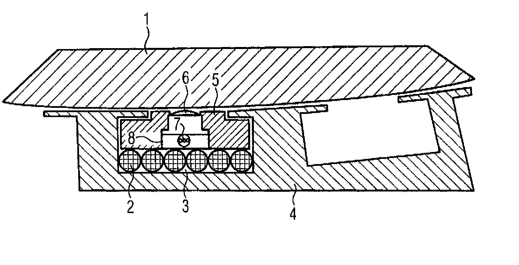
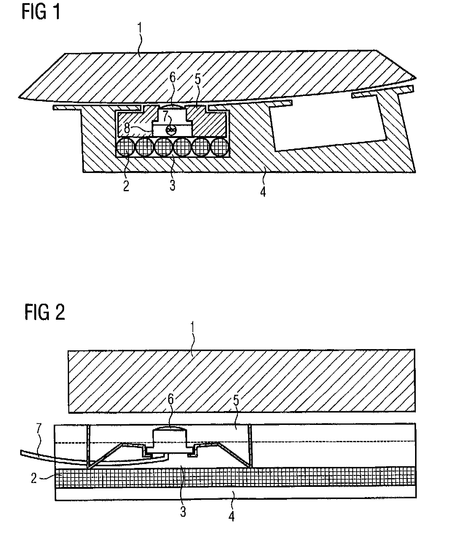
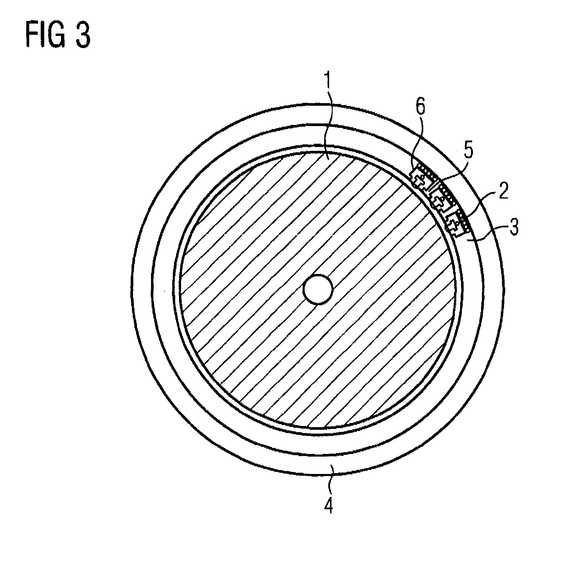
[0023]FIG. 1 schematically shows a sectional illustration (cross section) of a detail from an electrical machine having a rotor 1 and a stator 4. Slots 3 are made in the stator, with the winding 2 of the stator 4 running in said slots. For reasons of clarity, FIG. 1 shows only one layer with six turns of the winding 2. A blind hole 8 is made in a slot sealing wedge 5 of the slot 3, said blind hole being completely filled by the thermopile 6 (infrared temperature sensor). At the rotor 1 end, the blind hole 8 has a through-hole into which the detection side of the thermopile 6 projects, with this side of the thermopile 6 being composed of a transparent plastic on this side, said plastic having a surface which is configured in the form of a lens. Since the through-hole has a smaller diameter than the blind hole, the blind hole 8 is provided with a depth stop which prevents the thermopile 6 from being able to fall into the air gap between the rotor 1 and the stator 4. At the winding 2 e...


PUM


Abstract

The invention relates to a method and arrangement having an electric machine, comprising a stator (4) and a rotor (1) and an infrared temperature sensor, wherein the detection field of the infrared temperature sensor is directed at an outer surface of the rotor (1). The infrared temperature sensor is a thermopile (6) for radiometrically contactlessly detecting a temperature of the rotor (1), the thermopile being arranged in a slot of the stator (4) and being compatible with standard slot-sealing-wedge components of the electric machine with regard to assembly, and thus enables the operational monitoring of the thermal state of an electric machine in a novel manner, such that adapted power states can be achieved.

Description

CROSS-REFERENCES TO RELATED APPLICATIONS[0001]This application is the U.S. National Stage of international Application No. PCT / 2009 / 060701, filed Aug. 19, 2009, which designated the United States and has been published as International Publication No. WO 2011 / 020500.BACKGROUND OF THE INVENTION[0002]The invention relates to an arrangement having an electrical machine, and to a method for operating an electrical machine.[0003]In devices with complicated installation settings and extreme environmental conditions, it is often not readily possible to measure a temperature using contact thermometers. Particularly in the case of electrical machines, that is to say in the case of electric motors and generators, temperature measurement at rotating parts presents a problem in practice. Therefore, it is desirable to monitor the temperature of the rotor of electric motors and generators, for example, since such monitoring allows conclusions to be drawn about the operating state of the electrica...

Claims


Application Information

Patent Timeline
Patent Type & Authority Patents(United States)
IPC IPC(8): G05D23/08
CPCG01J5/00G01J5/0022G01J5/0096G01J5/04G01J5/042G01J5/044G01J5/048H02K11/0047H02K11/25
Inventor ZETTNER, JURGEN
Owner SIEMENS AG
Why Eureka
Try Eureka