Plant for the controlled-speed pneumatic transport of granular material and conveyance speed control process

a technology of pneumatic transport and granular material, which is applied in the direction of water supply tanks, transportation and packaging, mechanical equipment, etc., can solve the problem that the speed of a granular material is usually not maintained constant over tim

Active Publication Date: 2013-01-29
MORETTO SPA
View PDF12 Cites 54 Cited by
  • Summary
  • Abstract
  • Description
  • Claims
  • Application Information

AI Technical Summary

Benefits of technology

[0007]The main object, therefore, of the present invention is that of providing a plant for the reduced pressure transport of granular material along tubing in optimal flow speed or intensity conditions for the specific transported granular material, thus avoiding both the formation of granular material on the walls of the tubing and undesired stagnations of the granular material.
[0008]Another object of the present invention is to provide a plant for the reduced pressure transport of granular material that permits significantly reducing the operating costs with respect to the conventional plants.

Problems solved by technology

One of the most difficult problems to solve in the reduced pressure transport of granular material within conveyance ducts is that of being suitable for maintaining its transfer speed constant, even with the change of light or section of the ducts and / or configuration (curved, rectilinear) of the tubes along which the conveyance is carried out.
In the conventional plants, and in particular along the transport tubing, the speed of a granular material is usually not maintained constant over time.
The multilayer crusts or scales that are detached from the walls constitute a source of pollution / contamination for the granular materials that are conveyed along the tubing after their detachment from the inner wall of the tubing itself.

Method used


Image

  • Plant for the controlled-speed pneumatic transport of granular material and conveyance speed control process
  • Plant for the controlled-speed pneumatic transport of granular material and conveyance speed control process
  • Plant for the controlled-speed pneumatic transport of granular material and conveyance speed control process

Examples


Embodiment Construction

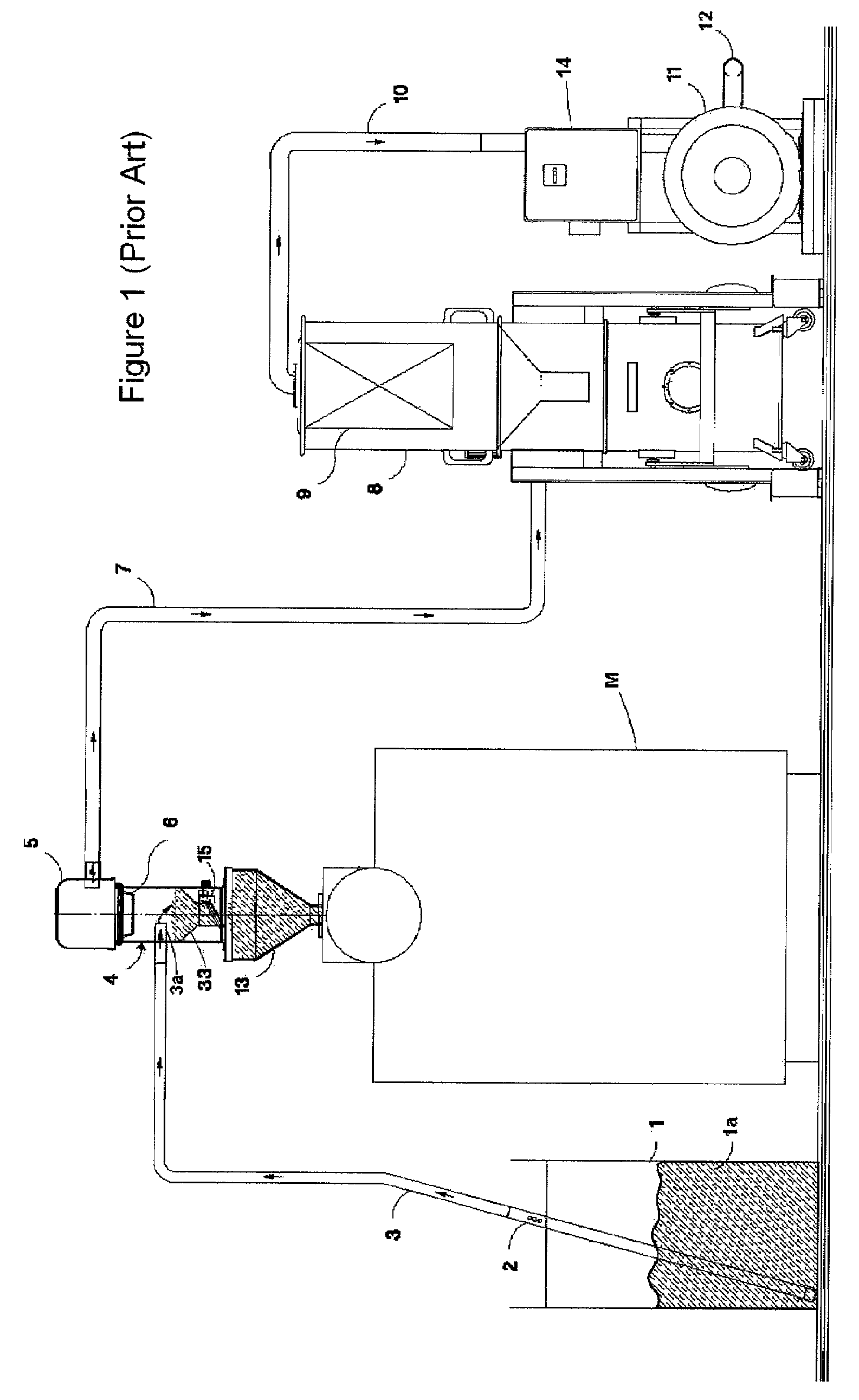
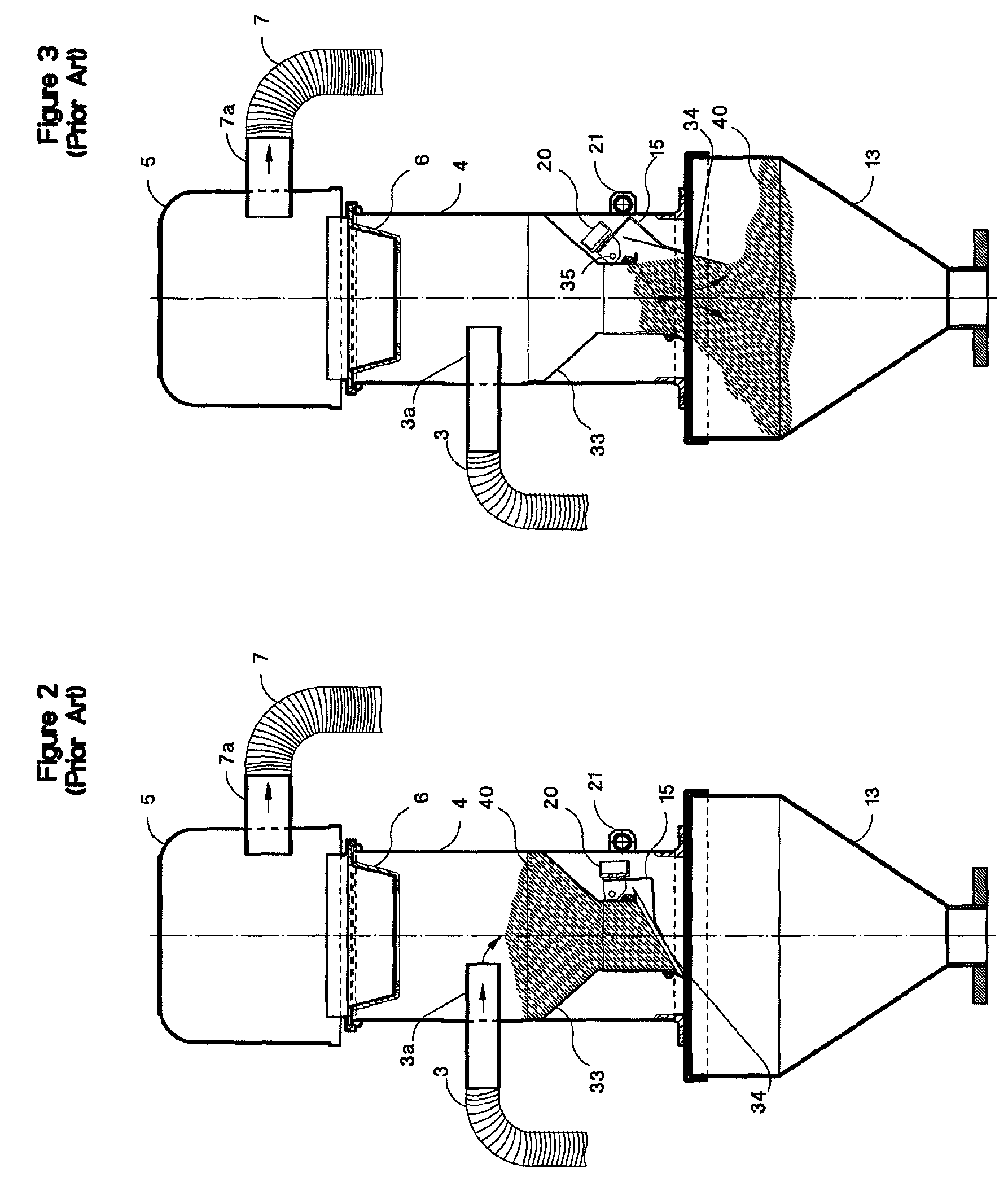
[0023]With reference first to FIGS. 1 to 3, it will be noted that a conventional reduced pressure transport plant of granular material comprises a container 1 of any suitable type containing a specific amount of granular material 1a to be transported, a fluidizing lance member 2 drawing in granular material 1a, e. g. formed by a substantially rigid tube, intended to capture material granules and mix them with air, as will be further described below. The lance member 2 is in fluid communication with one end of a tube or hose 3, which can be of both rigid and flexible type and whose other end penetrates in an intermediate portion of a hermetically-sealed receiver-meter device 4 and defines a discharge mouth 3a.

[0024]Within the receiver-meter device 4, at a lower level than that of the discharge mouth 3a, a small metering hopper 33 is provided equipped with lower discharge mouth that can be opened and closed by a bottom flap 34 supported by a projecting arm 15 in turn pivoted at 35 to...


PUM


Abstract

A plant for transport of granular material comprising container for granular material to be transported, receiver-meter group designed to receive granular material from container, conveyance duct of granular material from container to receiver-meter group, depressurization-pressurization means arranged to suction / inject a gaseous medium from / into container, and vacuum duct between receiver-meter group and depressurization-pressurization means, thereby creating a flow of granular material and gaseous medium in at least one conveyance duct or line directed to receiver-meter group and a flow of gaseous medium between receiver-meter group and depressurization-pressurization means, the plant comprising detection means of parameters of flow located in vacuum duct or line, adjusting means of the power of depressurization / pressurization means and electronic control means designed to receive in input control signals from speed detection means and to emit control signals in output for driving adjusting means.

Description

FIELD OF INVENTION[0001]The present invention regards a plant for the controlled-speed pneumatic transport of granular material, particularly but not exclusively suitable for the transport of granular material made of plastic material, as well as a process related thereto.BACKGROUND OF INVENTION[0002]With the terms “granules” or “granular”, it is intended to indicate in the present description and in the claims the small scales, sheets or plates produced by the grinding-crushing of slab, sheet, film and the like plastic material. In the plants for working and / or transforming plastic materials reduced into granules, granular material is transported from a storage container to one or more machines designed to use such a material and usually comprising injection or thermoforming presses, by means of a pneumatic conveyance or transport system, preferably operating under reduced pressure. The transport system must ensure a minimum flow rate of granular material, thereby ensuring a contin...

Claims


Application Information

Patent Timeline
Patent Type & Authority Patents(United States)
IPC IPC(8): B65G53/66
CPCB65G53/66B65G53/24Y10T137/0396Y10T137/86187B65G53/40B65G53/58B65G53/52
Inventor MORETTO, RENATO
Owner MORETTO SPA
Why Eureka
Try Eureka