Axial flow pump with a spiral-shaped vane

Active Publication Date: 2013-02-05
HANGTIANTAIXIN TECH CO LTD
View PDF29 Cites 10 Cited by
  • Summary
  • Abstract
  • Description
  • Claims
  • Application Information

AI Technical Summary

Benefits of technology

[0016]The axial flow pump in accordance with the invention has the advantage that pressure differentials of, for example, 100 hPa, 150 hPa or 200 hPa can be achieved and that it can be used as an implantable blood pump. It is also advantageous that the axial flow pump in a

Problems solved by technology

The axial flow blood pumps of the prior art have the disadvantage that either the contact area with the main volume flow of the blood is comparatively large due to the closed rotor body and the hub or, in the case of a hollow cylindrical rotor, the achievable pressure is very small due to the constant pitch of the vane and the o

Method used


Image

  • Axial flow pump with a spiral-shaped vane
  • Axial flow pump with a spiral-shaped vane
  • Axial flow pump with a spiral-shaped vane

Examples


second embodiment

[0044]The rotor caps 13, 17 have the advantage that larger permanent magnets 14.1 and 15.1 can be arranged therein, for example a ring-shaped permanent magnet 14.1 in the rotor cap 17 at the inlet side which can absorb larger axial forces. Since the axial force resulting due to the pressure differential between the inlet and the outlet has to be completely absorbed by the magnetic bearings with a contact-free support of the rotor, a greater pressure differential can be generated using the axial flow pump in accordance with the If required, instead of the permanent magnets, electromagnets can also be provided in the rotor caps with which the position of the rotor can be actively stabilised.

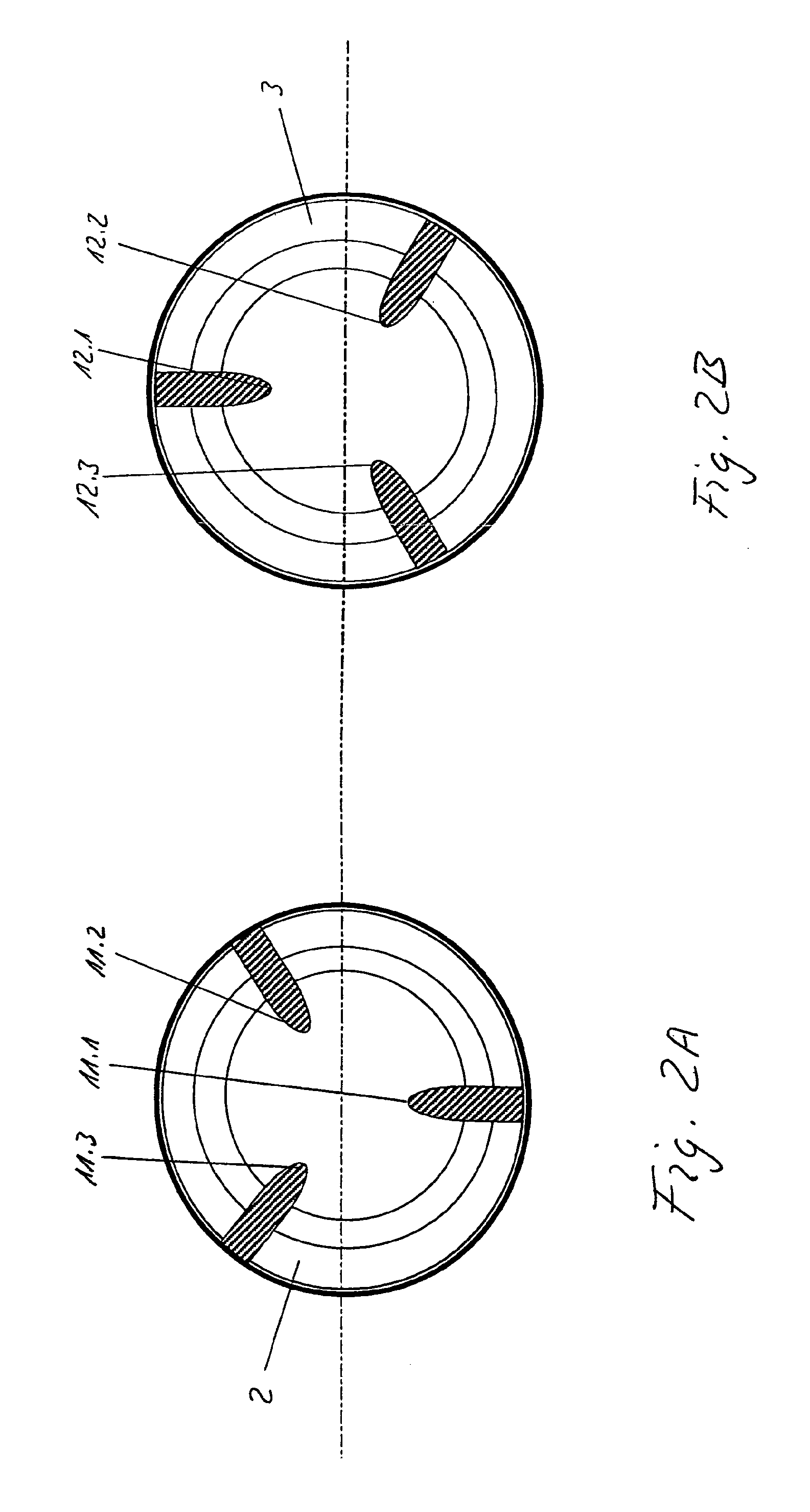
[0045]FIGS. 7A and 7B show cross-sections through the inlet region and the outlet region of the axial flow pump in accordance with the embodiment shown in FIG. 6. In this embodiment, three respective guide vanes 11.1-11.3, 12.1-12.3 are arranged in the inlet region and in the outlet region respect...

first embodiment

[0049]FIG. 11 shows a longitudinal section through a further embodiment of an axial flow pump in accordance with the present invention. The embodiment shown differs from the first embodiment in accordance with FIG. 1 in particular in that the pump 10 includes an additional pump stage 25 whose centre is closed towards the outlet 3. The additional pump stage 25 can be formed in the rotor 5, for example, as shown in FIG. 11. It is, however, also possible to provide a separate rotor for the additional pump stage which can be fitted with its own drive if necessary. As shown in FIG. 11, the additional pump stage can include a hub 24 and one or more transport elements 27 which can e.g. be made as vanes. The additional pump stage can be made axially or semi-axially. A pump of this type with an additional pump stage represents a separate and independent invention which can be protected in its own patent application.

[0050]In a preferred embodiment variant, the pump with an additional pump sta...


PUM


Abstract

An axial flow pump (10) is presented which includes a housing (1) with an inlet (2) and outlet (3) and a magnetically active rotor (5) in the housing which is provided with a passage (6) in the interior and with at least one spiral-shaped vane (7) in the passage, wherein the pitch of the vane (7) varies in the axial direction. The axial flow pump (10) furthermore includes an electromagnetic drive (4, 8) with a stator (8) which is arranged at the housing and cooperates with a magnetically active rotor.

Description

CROSS REFERENCE TO RELATED APPLICATIONS[0001]This is the U.S. national stage of International application PCT / EP2006 / 006344, filed Jun. 30, 2006 designating the United States which claims the benefit of European application 05405423.4, filed Jul. 1, 2005.BACKGROUND OF THE INVENTION[0002]The invention relates to an axial flow pump.[0003]Pumps for applications with small pressure differentials of typically 100 hPA to 150 hPa and comparatively large volume flows, such as blood pumps, for example, are advantageously designed as axial flow pumps. Document WO 96 / 18358 describes a blood pump of this type having a pipe-shaped pump housing in which a rotor is in each case rotatably supported in a bearing at the ends. The described rotor includes a cylindrical rotor body, with a hub adjacent to it on the inlet side and an end piece adjacent to it on the outlet side, each of which run out into a bearing spigot. Furthermore, a plurality of curved vanes are provided on the rotor body and a perma...

Claims


Application Information

Patent Timeline
IPC IPC(8): F04B35/04F04B35/00
CPCA61M1/101F04D3/02F04D13/0646F04D29/048F04D29/181A61M1/1015A61M1/122A61M1/125A61M60/82A61M60/422A61M60/148A61M60/237A61M60/812A61M60/122
Inventor BAYKUT, DOANBAYKUT, GOEKHANHIRT, FELIX
Owner HANGTIANTAIXIN TECH CO LTD
Why Eureka
Try Eureka