Microcavity structure and encapsulation structure for a microelectronic device
a microelectronic device and microcavity technology, applied in the direction of microstructural devices, microstructure technology, lamination, etc., can solve the problems of not being able to achieve a pressure less than about 10sup>3 /sup>mbar, risk of damage to the device or altering the proper operation, and not being able to fabricate release holes with dimensions larger than 5 m
- Summary
- Abstract
- Description
- Claims
- Application Information
AI Technical Summary
Benefits of technology
Problems solved by technology
Method used
Image
Examples
third embodiment
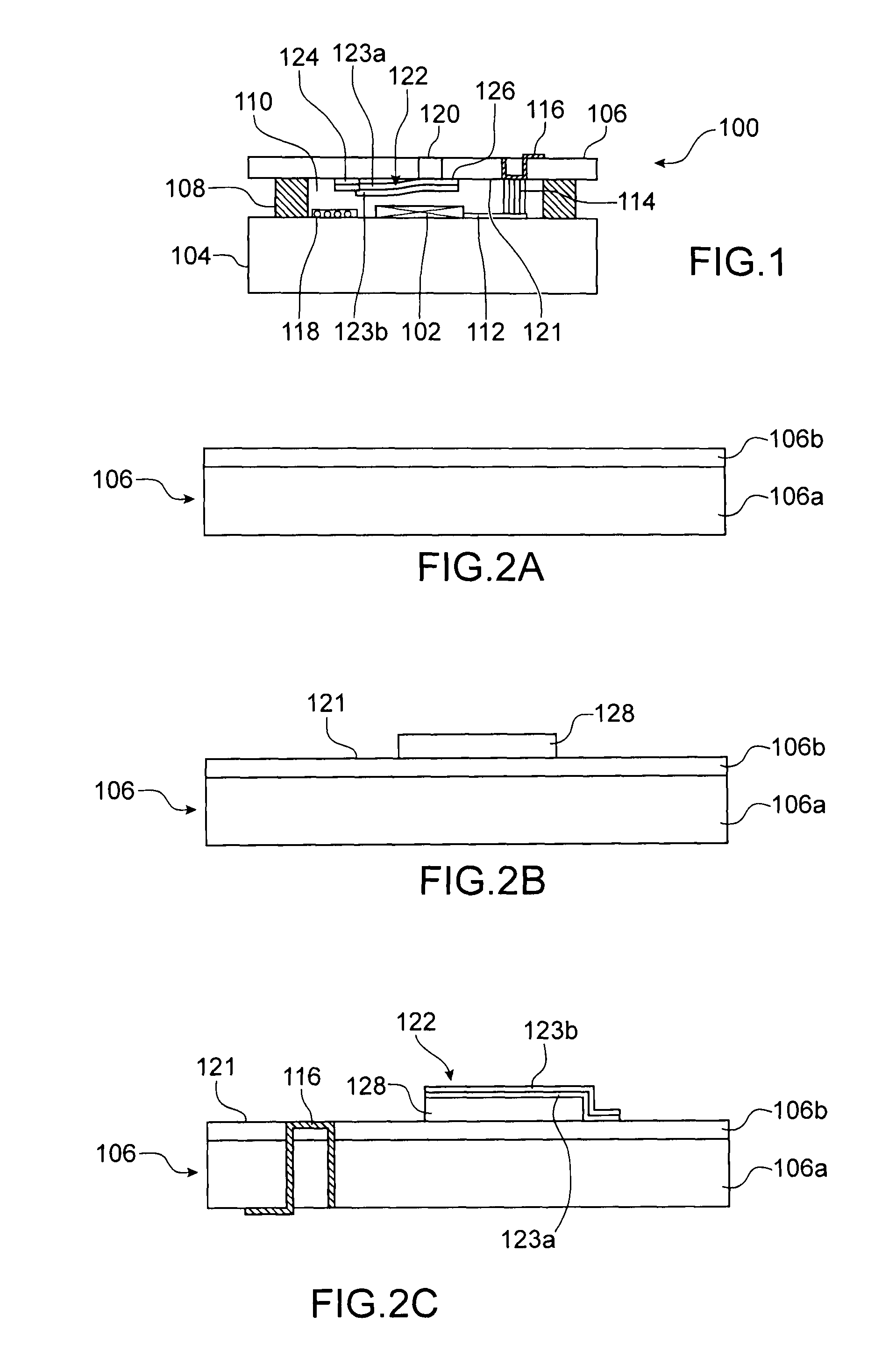
[0053]FIGS. 1, 3 and 4 show the microcavity structures serving as an encapsulation structure for a microelectronic device, respectively according to a first, a second and a third embodiment;
first embodiment
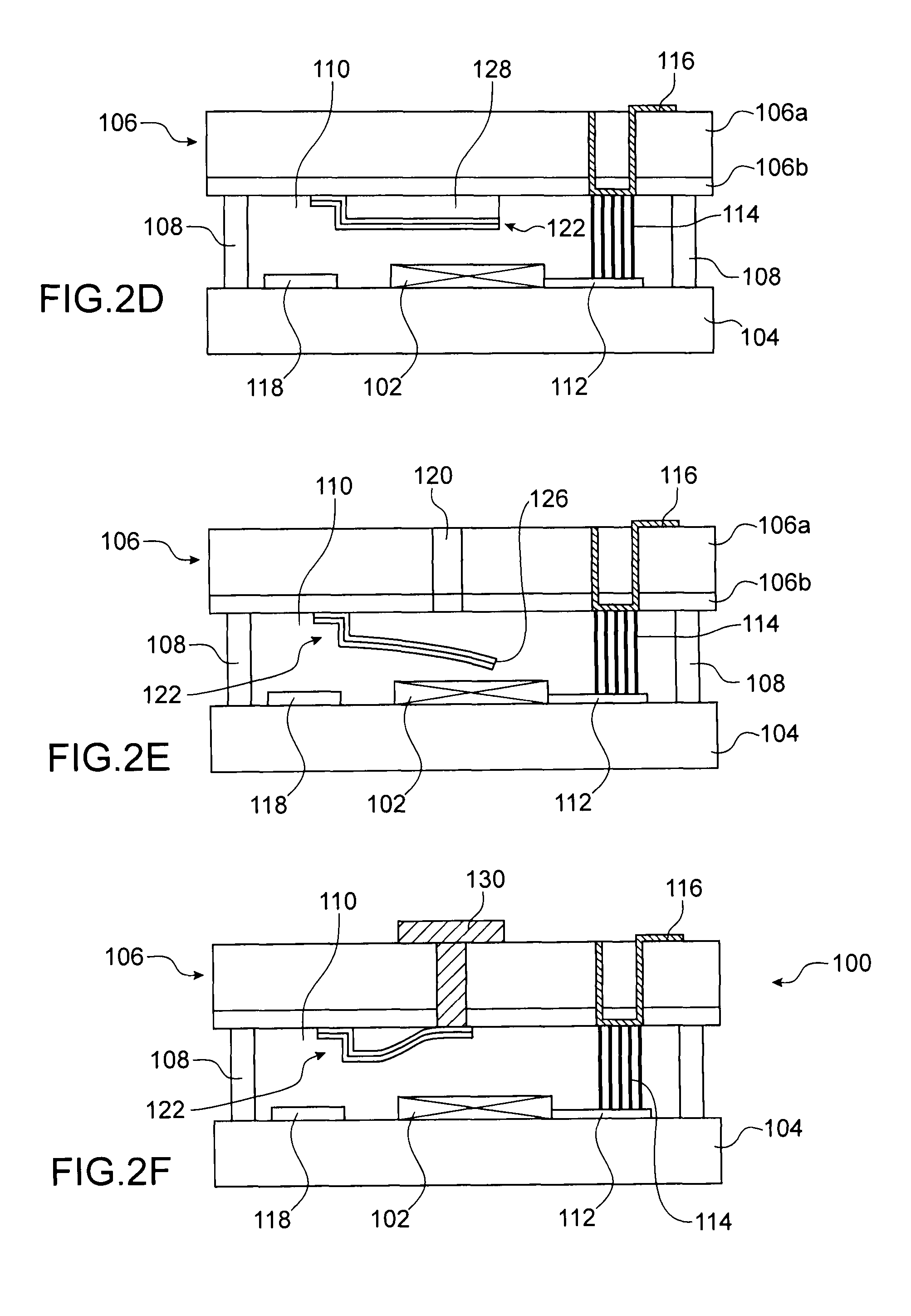
[0054]FIGS. 2A, 2B, 2C, 2D, 2E and 2F show the stages of a method of producing a microcavity structure corresponding to a method of encapsulation for a microelectronic device, ;
[0055]FIGS. 5A, 5B, 5C, 5D, 5E, and 5F show the stages of a method of producing a microcavity structure corresponding to a method of encapsulation for a microelectronic device, according to the third embodiment; and
[0056]FIG. 6 show an example of a closing flap for a microcavity structure.
[0057]Identical, similar or equivalent parts of the various figures described hereafter have the same numerical references so as to facilitate passing from one figure to another.
[0058]The different parts shown on the figures are not necessarily shown on a uniform scale, in order to make the figures clearer.
[0059]The different possibilities (variants and embodiments) should be understood as non-exclusive with respect to each other and can be combined one with another.
DETAILED DESCRIPTION OF PARTICULAR EMBODIMENTS
[0060]Referen...
second embodiment
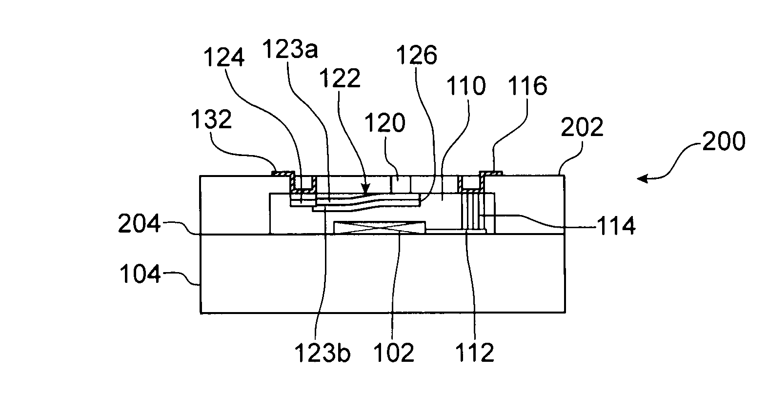
[0086]Reference is made to FIG. 3 which shows a microcavity structure 200, serving as an encapsulation structure for the microelectronic device 102, according to a
[0087]With respect to the encapsulation structure 100 shown in FIG. 1, the structure 200 comprises a second substrate 202, e.g. made of a semiconductor, such as silicon, forming a cover and attached to the first substrate 104 by direct sealing at the level of the interface 204. In this second embodiment, the structure 200 does not comprise a sealing cord between the two substrates 104, 202. In addition, in this second embodiment, the getter material 118 is not present inside the microcavity 110. The fixed end 124 of the closing flap 122 is electrically linked to an electrical contact 132. Thus the closing flap 122 may be actuated by heating using the Joule effect, obtained by intermediary of an electrical current applied to the electrical contact 132. In addition, when the closing flap 122 comprises one of these portions 1...
PUM
| Property | Measurement | Unit |
|---|---|---|
| thickness | aaaaa | aaaaa |
| thickness | aaaaa | aaaaa |
| pressure | aaaaa | aaaaa |
Abstract
Description
Claims
Application Information
 - R&D
- Intellectual Property
- Life Sciences
- Materials
- Tech Scout
- Unparalleled Data Quality
- Higher Quality Content
- 60% Fewer Hallucinations
Browse by: Latest US Patents, China's latest patents, Technical Efficacy Thesaurus, Application Domain, Technology Topic, Popular Technical Reports.
© 2025 PatSnap. All rights reserved.Legal|Privacy policy|Modern Slavery Act Transparency Statement|Sitemap|About US| Contact US: help@patsnap.com


