Dynamic routing of optical signals in optical networks

a technology of optical networks and optical signals, applied in the field of dynamic routing of optical signals in optical networks, can solve the problems of high blocking probability on a congested network, inadequate transparent network, etc., and achieve the effect of eliminating the availability of the only link and minimizing the risk

Inactive Publication Date: 2013-02-05
TELECOM ITALIA SPA
View PDF15 Cites 10 Cited by
  • Summary
  • Abstract
  • Description
  • Claims
  • Application Information

AI Technical Summary

Benefits of technology

[0037]The objective of the present invention is to provide a routing method that solves the problems of the known methods. This objective is achieved by the present invention, relating to a method for dynamic routing of optical signals in an optical network, as claimed in the appended claims.
[0045]The cost function also depends on the iteration for which the solution is being evaluated. The greater the number of failed iterations, the more the procedure favours solutions on links with greater wavelength availability or on nodes with greater regenerator availability. The solution provided by the method satisfies, by construction, the physical degradation constraints because wavelength continuity and the signal quality requirements fulfillment are guaranteed. In the case in which a solution to the problem is not found in this phase, a non-linear search procedure is then applied, in a way explained in detail later on.

Problems solved by technology

Regarding the above-cited publication of Li Bo et al., the U.S. Pat. No. 6,538,777, and the publication of K. Taira et al., the Applicant observes that all the described solutions do not take signal degradation into account, and so turn out to be inadequate for a transparent network.
With regard to US 2003 / 0016414, the Applicant observes that this method does not assure the feasibility of a route (from the transmission degradation standpoint), resulting in a high blocking probability on a congested network where very few regenerators are available.

Method used


Image

  • Dynamic routing of optical signals in optical networks
  • Dynamic routing of optical signals in optical networks
  • Dynamic routing of optical signals in optical networks

Examples


Embodiment Construction

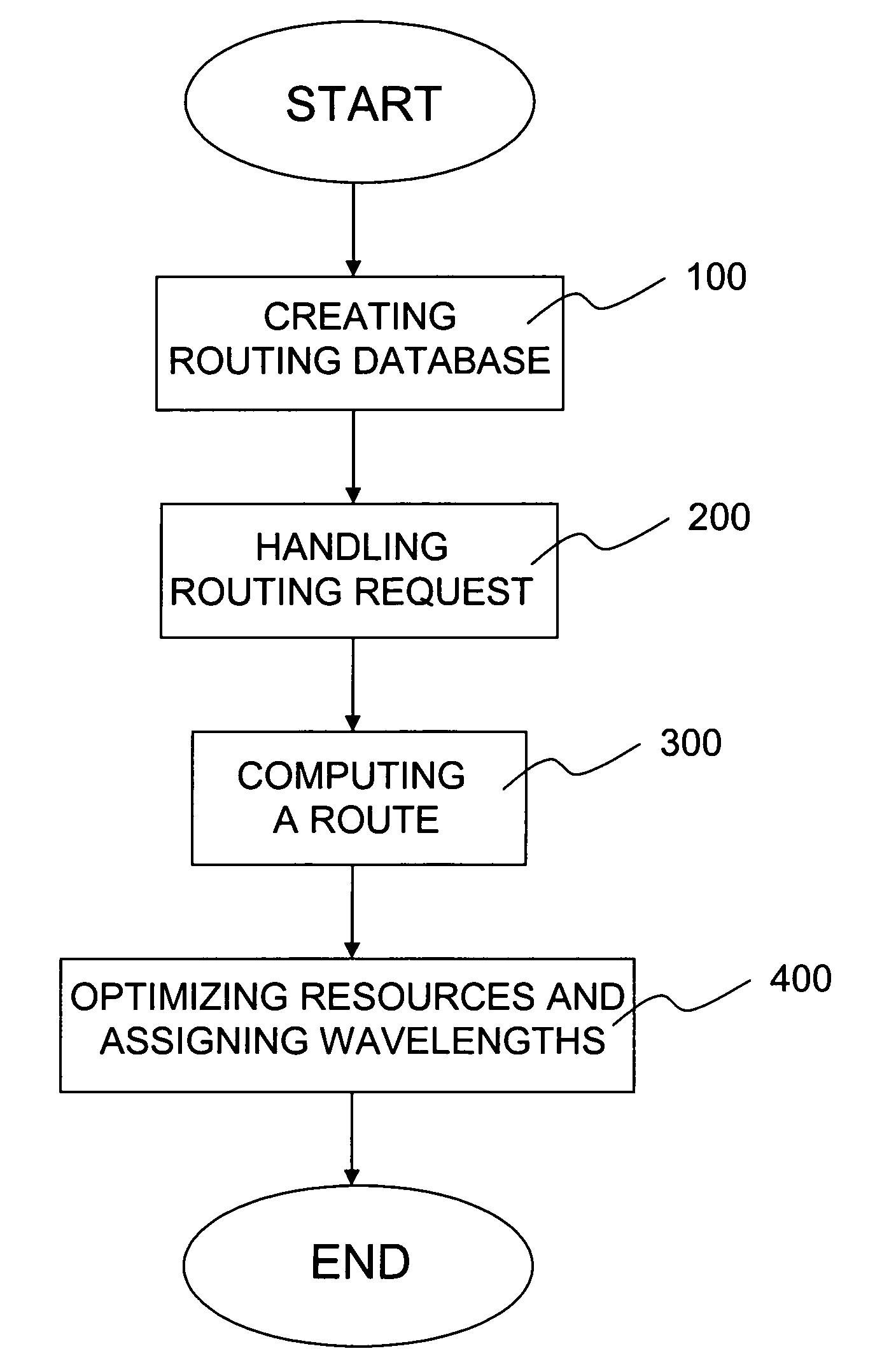
[0080]With reference to FIG. 8 it is shown the flowchart of the main steps of the method according to a preferred embodiment of the present invention.

[0081]The main phases of the method are the following:[0082]Creating a Routing Database (RDB) (block 100);[0083]Handling a routing request (block 200);[0084]Computing a route (block 300); and[0085]Optimizing resources along the computed route and assigning the wavelengths (block 400).

[0086]Block 100 provides for the creation of the necessary preliminary information for route searching. In particular, block 100 comprises the following phases:[0087]collecting the topological information of the network and the nodes description; and[0088]computing a vector (a set of ordered values) for each bundle of homogenous interfaces (i.e. interfaces with the same characteristics with respect to routing purposes, e.g. TE-links) deployed in the network, the vector's elements quantifying the degradation that the optical signal undergoes in travelling o...


PUM

PropertyMeasurementUnit
wavelengthsaaaaaaaaaa
wavelengthaaaaaaaaaa
currentaaaaaaaaaa

Abstract

A method for dynamic routing an optical signal in an optical network is provided, including: executing a shortest-path algorithm receiving input concerning a source node, a destination node and the topology of the network, providing a shortest-path tree comprising nodes and arcs connecting the nodes, the shortest-path tree comprising branches along which an effective attenuation is no greater than a predetermined limit, each branch comprising an end node and each end node being associated with a corresponding set of wavelengths; checking, for each end node having no wavelength conversion resources and for each wavelength, if the end node is connected to at least another node external to the branch through the wavelength; excluding, for any end node if the result of the checking is negative for at least one wavelength, the at least one wavelength from the corresponding set of wavelengths, thus updating the topology; and re-executing the shortest-path algorithm.

Description

CROSS REFERENCE TO RELATED APPLICATION[0001]This application is a national phase application based on PCT / EP2006 / 012454, filed Dec. 22, 2006, the content of which is incorporated herein by reference.TECHNICAL FIELD OF THE INVENTION[0002]The present invention relates to dynamic routing of optical signals in optical networks.BACKGROUND ART[0003]In the complex scenario of telecommunications networks, a trend has been establishing itself over the last few years to consolidate certain technologies already in use over the last decade (IP and Ethernet) and to simplify the protocol stack, enriching the pre-existing technologies with new functionality (Pseudowire on Ethernet, QoS on MPLS-TE) with the aim of achieving simpler and cheaper-to-maintain networks.[0004]However, there is no lack of innovative solutions in a market continually in search of solutions aimed at curbing network operating expenses (OPEX) and the possibility of quickly introducing new services on the market, the prolifera...

Claims


Application Information

Patent Timeline
Patent Type & Authority Patents(United States)
IPC IPC(8): H04J14/02H04L12/28G02F1/00
CPCH04L45/12
Inventor D'ALESSANDRO, ALESSANDROMURATORI, MARCO
Owner TELECOM ITALIA SPA
Why Eureka
Try Eureka