Portable and collapsible loading and unloading ramp

a loading and unloading ramp, portable technology, applied in the direction of loading/unloading vehicle arrangment, transportation items, refuse collection, etc., can solve the problems of slowing down the inertia of the cargo, reducing the amount of energy required to move the cargo, and traditional loading ramps are not practical for lifting trucks. , to achieve the effect of convenient use and movement, long design, and convenient use by a single operator

Active Publication Date: 2013-02-12
MIKLOS ROBERT NANDOR
View PDF19 Cites 5 Cited by
  • Summary
  • Abstract
  • Description
  • Claims
  • Application Information

AI Technical Summary

Benefits of technology

[0013]An important object of this apparatus is that it requires no permanent attachment and can be easily used and moved from one truck bed to another by a single person.
[0014]Another important object of this apparatus is the design of a self braking wheel system that slows the inertia of the cargo on a downward slope, thus creating a safer product that is easier to use by a single operator.
[0015]Another object of this apparatus is that it incorporates a longer design than most loading ramps. This additional length reduces the steepness of the slope angle which reduces the amount of energy required to move the cargo up hill and slows the cargo's inertia moving down hill. This additional length provides a use of this product on lifted trucks with modified suspensions. Traditional loading ramps are not practical for use on lifted trucks because the slope angle is too steep. This invention solves that problem.
[0016]Another object of this invention is that it eliminates the need for a trailer which is the most common conveyance vehicle used to transport a personal watercraft. Many lakes operate with a limited amount of boat trailer parking spaces and when full, patrons with trailers are usually turned away or sent to a waiting area. This invention solves that problem because it eliminates the need for a trailer, therefore allowing the patron access to the lake with their personal watercraft in a truck bed. The long length of this apparatus enables a personal watercraft to be launched into the water in areas that a trailer and or truck can not access or would get stuck in a muddy shoreline. The invention can also be used to launch a watercraft over small seawalls, boulders or other impediments that would restrict trailer access. Prior art of loading ramps that are commonly used with pick-up trucks, typically tend to be shorter in length then this said invention because of either heavy weight or too much flex associated with longer length ramps. The advantage of this invention is that it combines long length with light materials and is still able to maintain a rigid shape by a bottom mounted tension cable, similar to a cable suspended bridge that is turned up side down.
[0017]Another object of this invention is the design reduces weight. Long loading ramps are usually very heavy because of the relationship between span and size. The longer the distance of span the larger the size and weight of structural load bearing members need to be. This invention solves the problem of having to use large heavy structural members to span a greater distance. This invention uses a light weight tensioned wire cable to transfer the cargo's weight load from the middle of the ramp to each end which results in a stronger, lighter and more rigid design that can span a greater distance.
[0018]It is an additional object of this apparatus to be compact for easy stowage. The invention when retracted for stowage occupies only ten percent of the perimeter cubic space when used in its open operable state. This invention saves valuable cargo space.

Problems solved by technology

This additional length reduces the steepness of the slope angle which reduces the amount of energy required to move the cargo up hill and slows the cargo's inertia moving down hill.
Traditional loading ramps are not practical for use on lifted trucks because the slope angle is too steep.

Method used


Image

  • Portable and collapsible loading and unloading ramp
  • Portable and collapsible loading and unloading ramp
  • Portable and collapsible loading and unloading ramp

Examples


Embodiment Construction

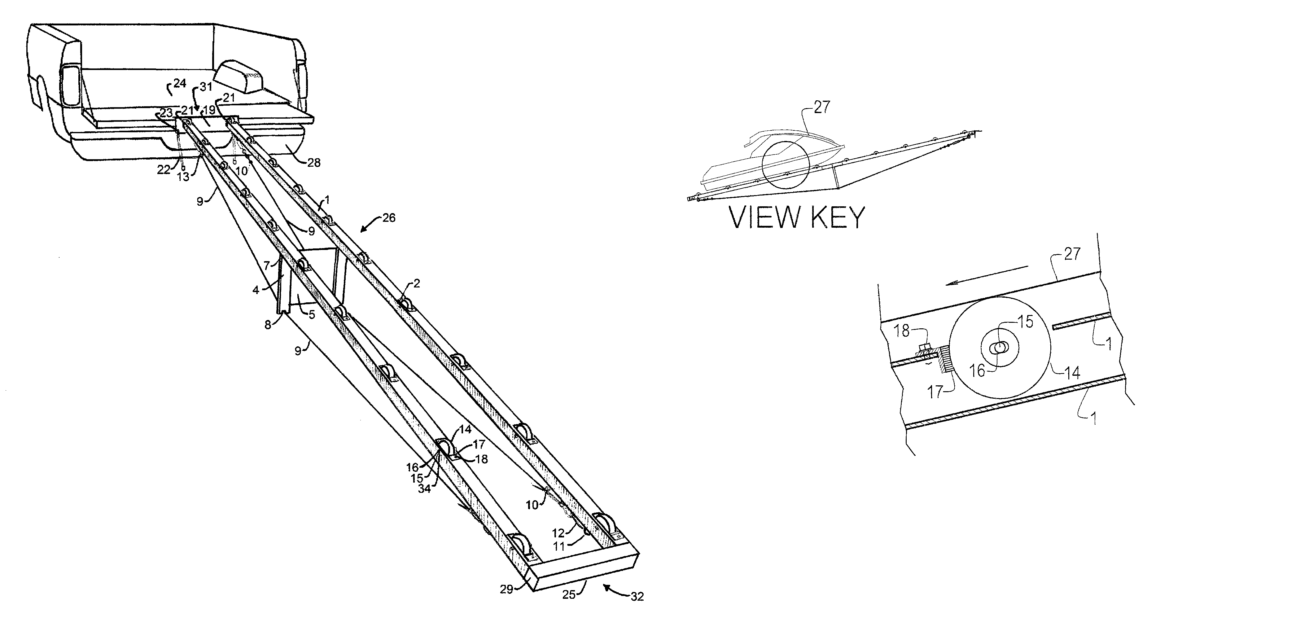
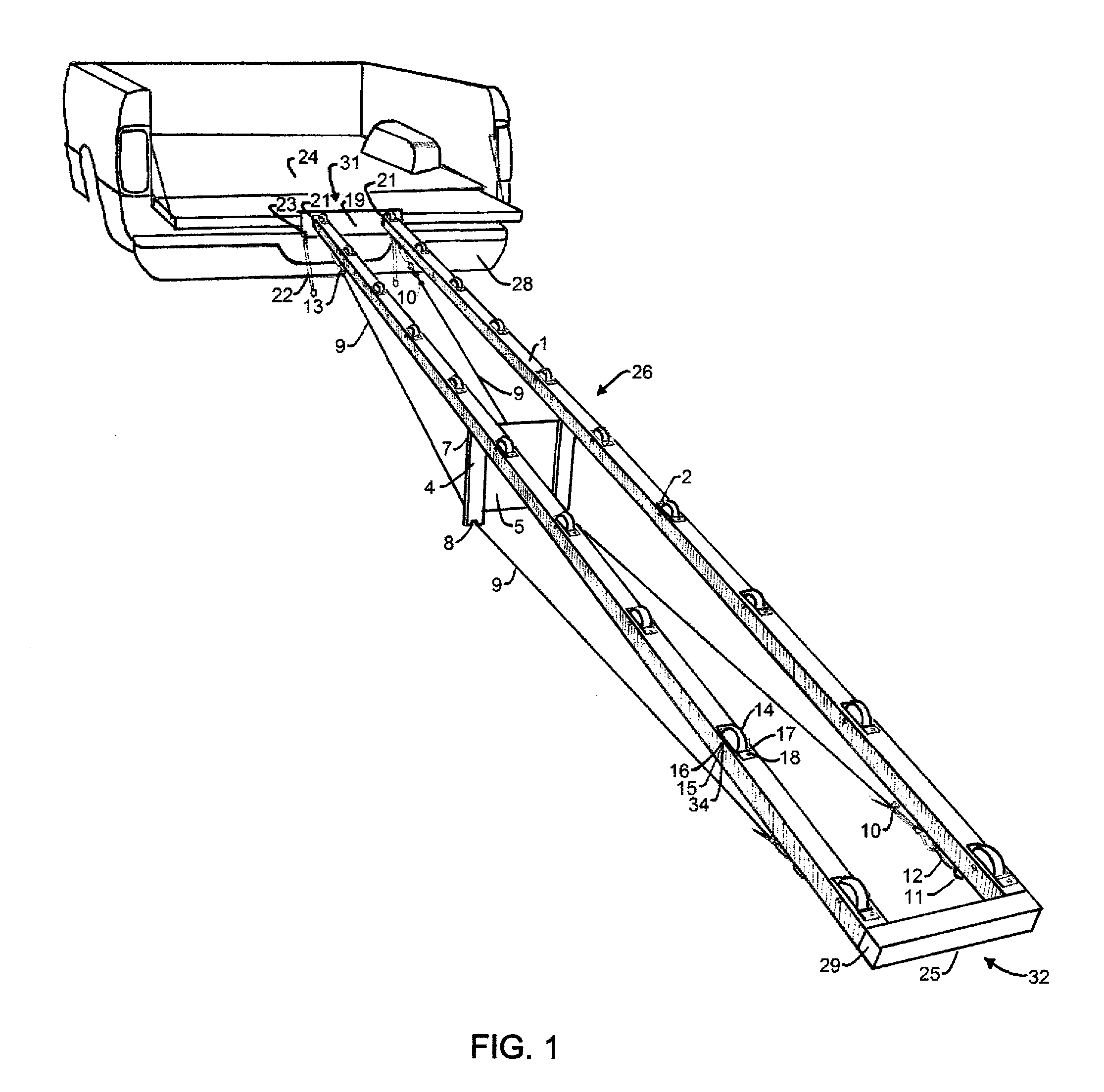
[0066]Although this invention may take specific forms that vary slightly from the illustrated drawings to accommodate different cargo 27 weights, the ideal practice of this invention will follow closely to the drawings illustrated. Referring now to the drawings and particularly FIGS. 1, 3, &4 will represent the preferred embodiment and use of the fully assembled apparatus 26.

[0067]Using the fully assembled apparatus 26 requires the apparatus top end 31 known as the mooring plate assembly 19 to be moored on a conventional pick up truck bed 24 or similar and secured in place using a conventional tie down strap 22 connected to the mooring plate assembly 19 through a hole 23 and securing the other end of the conventional tie down strap 22 to a secure location deemed by the user such as a steel bumper 28. The apparatus bottom end 32 of the fully assembled apparatus 26 should rest on a ground surface 25 that is horizontally parallel with the mooring plate assembly 19 either out of water o...


PUM


Abstract

A portable ramp for non-wheeled cargo such as, but not limited to, a personal watercraft, designed to assist the movement of cargo in and out of a truck or trailer bed. The invention is both light weight and collapsible for easy portability and stow ability. The invention consists of a composition of parts that facilitate quick assembly and disassembly. A plurality of square hollow tube rails, a plurality of center masts, a connection sleeve and a plurality self-braking wheels assist in the conveyance of cargo uphill with free spinning wheels and slow the cargo's movement downhill by engaging the wheels into a friction pad. The invention uses a wire cable that runs along the bottom of the said rails to strengthen the assembled ramp. This wire cable has adjustable tension and is engaged by extending the center mast downward creating a triangle shape.

Description

STATEMENT REGARDING FEDERALLY SPONSERED RESEARCH OR DEVELOPMENT[0001]No federally sponsored research and development was conducted.BACKGROUND OF THE INVENTION[0002]1. Field of the Invention[0003]This invention generally relates to apparatus for loading and unloading non-wheeled cargo into the bed of a truck or trailer with an emphasis on light weight portability, compact stow ability without permanent attachment of any hardware to the truck or trailer. The apparatus is constructed from commonly available materials and components for economical manufacture.[0004]2. Description of Prior Art[0005]Loading ramps have been in use for many centuries and have evolved into many configurations utilizing many different materials to convey cargo from one area to another, usually involving a slope. This invention is intended for non-wheeled cargo such as, but not limited to a personal watercraft commonly known as a jet ski. There have been prior art inventions that are intended for personal wate...

Claims


Application Information

Patent Timeline
Patent Type & Authority Patents(United States)
IPC IPC(8): B65G13/11
CPCB65G69/30
Inventor MIKLOS, ROBERT NANDOR
Owner MIKLOS ROBERT NANDOR
Why Eureka
Try Eureka