Apparatus and method for grazing angle independent signal detection

a signal detection and grazing angle technology, applied in the field of apparatus and method for grazing angle independent signal detection, can solve the problem of poor correlation between echoes received back from the same object at different grazing angles, and achieve good correlation

Active Publication Date: 2013-02-12
USA AS REPRESENTED BY THE SEC OF THE NAVY THE
View PDF10 Cites 15 Cited by
  • Summary
  • Abstract
  • Description
  • Claims
  • Application Information

AI Technical Summary

Benefits of technology

[0004]Accordingly, an object of the invention is to permit good

Problems solved by technology

Unfortunately, echo signature varies with the angle of incidence, or grazing angle, at which the object is scann

Method used


Image

  • Apparatus and method for grazing angle independent signal detection
  • Apparatus and method for grazing angle independent signal detection
  • Apparatus and method for grazing angle independent signal detection

Examples


Embodiment Construction

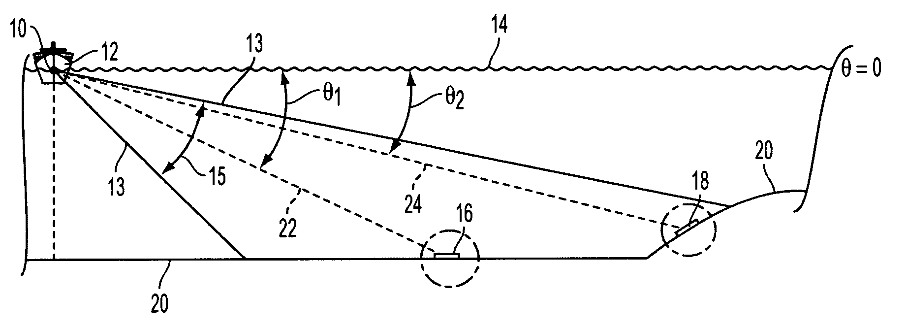
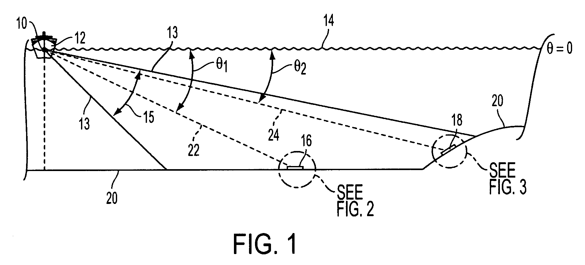
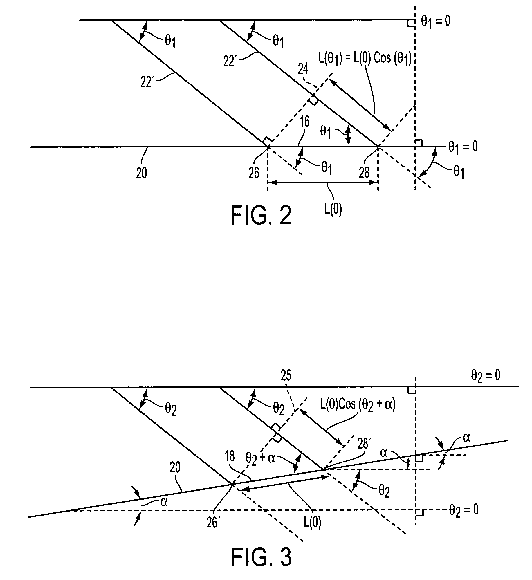
[0016]With reference to the drawing figures, wherein like numbers indicate like parts throughout the several views, FIG. 1 shows an embodiment of the invention employing sonar. A side scanning sonar 10 is mounted on ship 12 disposed on marine surface 14 above bottom 20, and generates a broad beam sonar signal 13 of azimuthal width 15. Beam 20 irradiates a broad swath of bottom 20 with a pulse of known spectral content, and receives back echoes, here in the form of complex pressure intensities, from bottom 20 and preferably records the echoes, for example by digitally sampling the echoes and recording the samples on a digital storage device for processing. Included among these echoes are returns from patches 16, 18 of bottom 20, which have respective lines of sight 22, 24 to sonar 10 at azimuthal angles θ1 and θ2. As illustrated in FIG. 1, bottom patches 16, 18 are at different distances from sonar 20, and at different orientations, i.e. different grazing angles, thereto. These patch...


PUM


Abstract

An apparatus and method for relating echoes from a surface or object produced by irradiation, such as by sonar or radar, from different grazing angles according to the relationship:
fs=cfx2cosθ
    • where fx is the spatial frequency corresponding to the size of the surface or object, θ the grazing angle, and fs the temporal frequency. In this manner one can relate to one another echoes from the same surface or object generated at different grazing angles, permitting good correlation between the echoes.

Description

CLAIM OF PRIORITY[0001]This application has the priority of U.S. Provisional Patent Application Ser. No. 61 / 216,566, filed May 18, 2009.STATEMENT OF GOVERNMENT INTEREST[0002]The invention described herein may be manufactured and used by or for the Government of the United States of America for governmental purposes without the payment of any royalties thereon or therefor.BACKGROUND OF THE INVENTION[0003]A basic function of radiative systems such as sonar or radar is to reliably correlate echoes received from an object scanned from different locations. This permits identification, classification, or imaging of objects or surfaces, examples of which might be, in a marine environment, sea shells, pebbles, rocks, shoals, patches of seafloor, terrain, naval mines, undersea pipes or cables, or sunken vessels. Unfortunately, echo signature varies with the angle of incidence, or grazing angle, at which the object is scanned, which means that echoes received back from the same object at diff...

Claims


Application Information

Patent Timeline
IPC IPC(8): G01S15/00
CPCG01S7/292G01S7/5273G01S13/89G01S15/8902G01S15/89G01S7/41G01S7/539
Inventor RIKOSKI, RICHARD J.
Owner USA AS REPRESENTED BY THE SEC OF THE NAVY THE
Why Eureka
Try Eureka