
Cladding alloy powder, alloy-clad member, and engine valve

a technology of cladding alloy and alloy, which is applied in the direction of machines/engines, metal-working devices, metal-layered products, etc., can solve the problems of reducing not having a satisfactory toughness, and not adequately exhibiting the properties of heat-resistant steel typically used as a valve material, so as to improve the toughness improve the wear resistance of the cladding alloy. , the effect of improving the toughness

Active Publication Date: 2013-02-19
TOYOTA JIDOSHA KK
View PDF14 Cites 11 Cited by
  • Summary
  • Abstract
  • Description
  • Claims
  • Application Information

AI Technical Summary

Benefits of technology

The invention provides a way to make a cladding alloy powder, an alloy-clad member, and an engine valve that are stronger and more durable against wear and corrosion. This is done by controlling the amount of carbon addition in the cladding alloy to avoid the formation of coarse carbides that can lead to fracture. By doing this, the cladding alloy's structure is improved, which enhances its impact strength, tensile strength, elongation, and other mechanical properties.

Problems solved by technology

Accordingly, the heat-resistant steels typically used as a valve material do not adequately exhibit these properties.
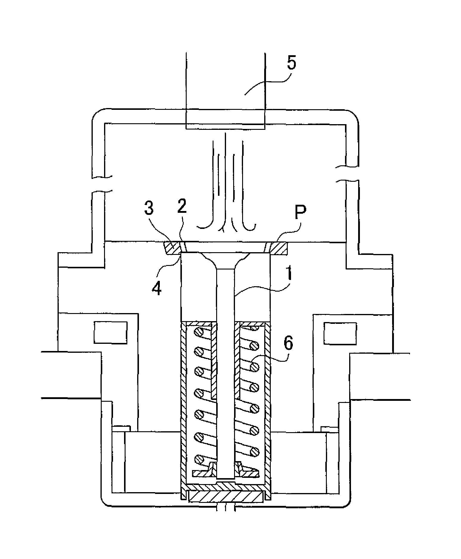
However, the cladding alloy described in Japanese Patent No. 2970670, while being able to provide the properties described above, does not have a satisfactory toughness, and cracking due to, for example, thermal impact, may be caused.
The reason for this is believed to be as follows: the hardness of the cladding alloy is increased due to the presence in the cladding alloy of coarse primary carbides of, for example, Mo, but these primary carbides form a fracture origin and thereby lower the toughness of the cladding alloy.
In addition, these coarse primary carbides have a shape that results in a high capacity to damage mating members and end up gouging the mating member material that comes into contact with the clad member, which also results in wear of the mating member material.

Method used


Image

  • Cladding alloy powder, alloy-clad member, and engine valve
  • Cladding alloy powder, alloy-clad member, and engine valve
  • Cladding alloy powder, alloy-clad member, and engine valve

Examples


example 1

[0041]A cladding alloy powder that satisfied the content conditions of C: 0.7 to 1.0 mass %, Mo: 30 to 40 mass %, Ni: 20 to 30 mass %, Cr: 10 to 15 mass %, and balance including Co and unavoidable impurities, was first prepared as a cladding alloy powder corresponding to an example of the invention.

[0042]Specifically, a cladding alloy (alloy in which Co formed the matrix) with the composition C: 0.9 mass %, Mo: 30 mass %, Ni: 20 mass %, Cr: 10 mass %, and balance including Co (Co: at least 35 mass %) and unavoidable impurities, was melted at a temperature of at least 1700° C. and a cladding alloy powder was produced using a gas atomizer in which an inert gas is used. This cladding alloy powder was classified into the 44 to 180 μm range. A Co-30Mo-10Cr-20Ni-0.9C cladding alloy powder was obtained as a result.

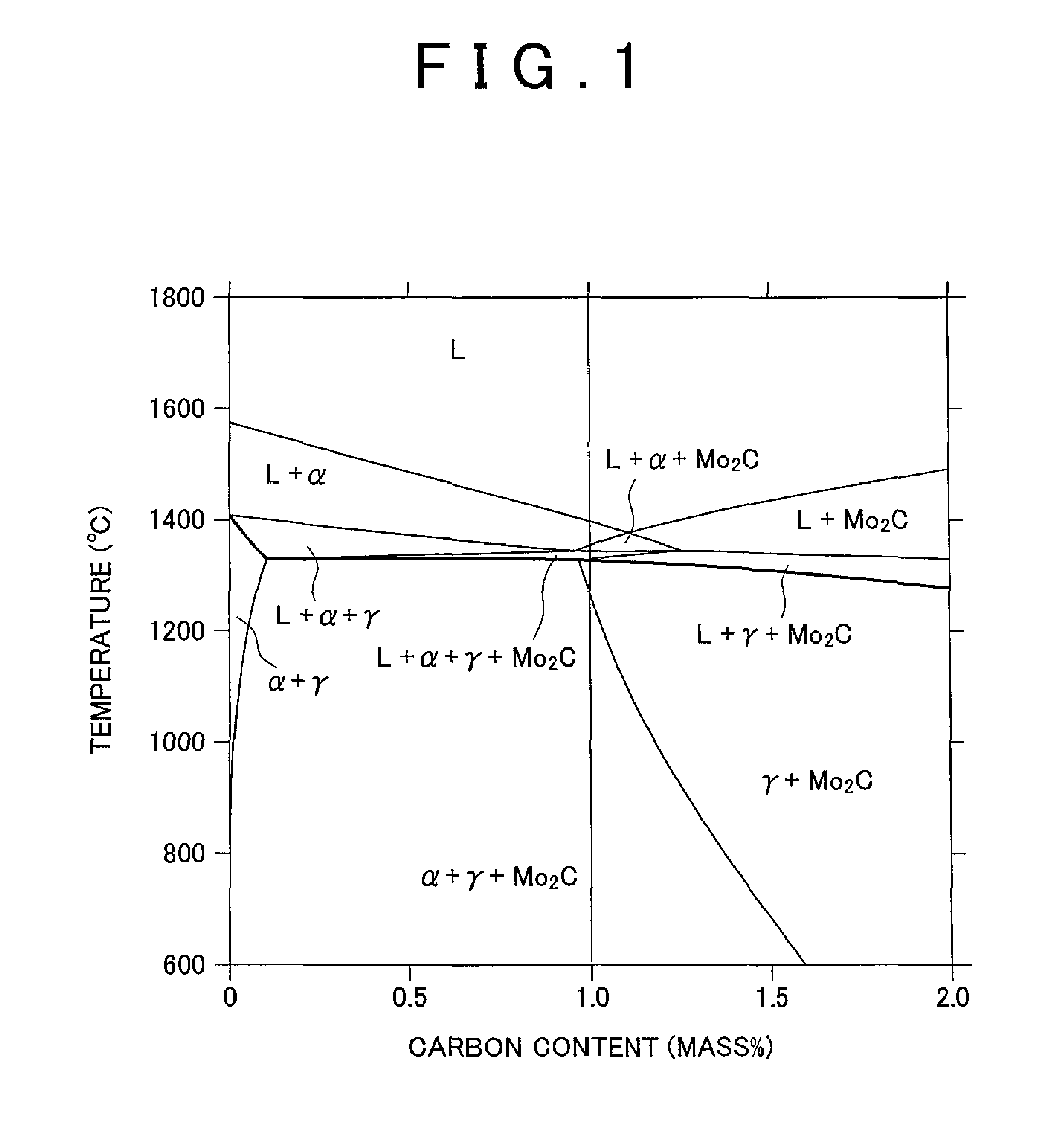
[0043]The 1.0 mass % upper limit for the C content in the cladding alloy powder was established as follows. Specifically, a phase diagram in which the C content was varied, as ex...

example 2

[0045]A cladding alloy powder that satisfied the content conditions of C: 0.2 to 0.5 mass %, Mo: 30 to 40 mass %, Ni: 20 to 30 mass %, and balance including Co and unavoidable impurities, was prepared as a cladding alloy powder corresponding to an example of the invention.

[0046]Specifically, a cladding alloy (alloy in which Co formed the matrix) with the composition C: 0.5 mass %, Mo: 30 mass %, Ni: 20 mass %, and balance including Co (Co: at least 35 mass %) and unavoidable impurities, was melted at a temperature of at least 1700° C. and a cladding alloy powder was produced using a gas atomizer in which an inert gas is used. This cladding alloy powder was classified into the 44 to 180 μm range. A Co-40Mo-20Ni-0.5C cladding alloy powder was obtained as a result.

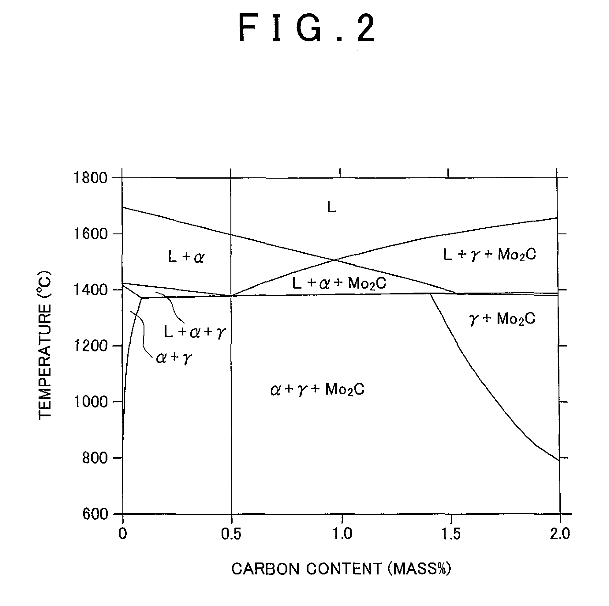
[0047]Using the previously indicated Thermo-Calc integrated thermodynamic computation system, the 0.5 mass % upper limit for the C content in the cladding alloy powder was established, as in Example 1, from a phase diagram in...

examples 3-1 and 3-2

[0064]Engine valves clad (overlaid) with the cladding region and test specimens for hardness testing were fabricated proceeding as in Example 1. The differences from Example 1 were as follows: a C content of 0.7 mass % was used in Example 3-1 and a C content of 1.0 mass % was used in Example 3-2.


PUM

PropertyMeasurementUnit
mass %aaaaaaaaaa
mass %aaaaaaaaaa
temperatureaaaaaaaaaa

Abstract

A cladding alloy powder consisting of: 0.7 to 1.0 mass % C; 30 to 40 mass % Mo; 20 to 30 mass % Ni; 10 to 15 mass % Cr; and a balance including Co and unavoidable impurities, or consisting of: 0.2 to 0.5 mass % C; 30 to 40 mass % Mo; 20 to 30 mass % Ni; and a balance including Co and unavoidable impurities.

Description

INCORPORATION BY REFERENCE[0001]The disclosure of Japanese Patent Application No. 2010-134324 filed on Jun. 11, 2010 including the specification, drawings, and abstract is incorporated herein by reference in its entirety.BACKGROUND OF THE INVENTION[0002]1. Field of the Invention[0003]The invention relates to a cladding alloy powder for cladding the surface of a base material and to an alloy-clad member and an engine valve that use this cladding alloy powder. The invention more particularly relates to a cladding alloy powder that is well suited for high-temperature environments and to an alloy-clad member and an engine valve that use this cladding alloy powder.[0004]2. Description of the Related Art[0005]Heat-resistant steel is used for machinery that is employed in high-temperature atmospheres, e.g., the intake valves and exhaust valves of internal combustion engines, in order to improve, for example, the wear resistance. In particular, the valve face of the engine valve and the lik...

Claims


Application Information

Patent Timeline
Patent Type & Authority Patents(United States)
IPC IPC(8): F16K1/42
CPCB23K35/3046B23K35/327B32B15/013C22C1/0433C22C19/00C22C19/07C22C27/04C22C30/00F01L3/02F01L3/04Y10T137/7036Y10T428/31678
Inventor HIGASHIYAMA, KIYOSHIANDO, KIMIHIKOKAMO, YUKI
Owner TOYOTA JIDOSHA KK
Learn More