Pattern forming method, substrate processing method and mold structure replication method

a substrate processing and mold technology, applied in the field of pattern forming method, substrate processing method and mold structure replication method, can solve the problems of high defect incidence, low accuracy, and resolution decline, and achieve the effect of efficiently forming a minute pattern, high accuracy and reducing the incidence of defects

Active Publication Date: 2013-02-19
FUJIFILM CORP
View PDF20 Cites 2 Cited by
  • Summary
  • Abstract
  • Description
  • Claims
  • Application Information

AI Technical Summary

Benefits of technology

[0009]An object of the present invention is to provide a pattern forming method, a substrate processing method and a mold structure replication method, which enable a mold structure to be highly accurately replicated by one-time imprinting, reduce the incidence of defects and efficiently form a minute pattern.
[0021]According to the present invention, it is possible to solve the problems with related art and provide a pattern forming method, a substrate processing method and a mold structure replication method, which enable a mold structure to be highly accurately replicated by one-time imprinting, reduce the incidence of defects and efficiently form a minute pattern.

Problems solved by technology

Consequently, there are such problems that the process becomes complex, the incidence of defects becomes high and there is a decrease in accuracy.
In this proposal, however, the gap between the photocatalytic pattern and a substrate into which the pattern is to be transferred causes a decrease in resolution, and thus it is difficult to form a minute pattern of nanometer size.

Method used


Image

  • Pattern forming method, substrate processing method and mold structure replication method
  • Pattern forming method, substrate processing method and mold structure replication method
  • Pattern forming method, substrate processing method and mold structure replication method

Examples


example 1

—Mold Structure—

[0079]A quartz structure having on its surface a line and space pattern of 600 nm in half pitch and 350 nm in depth was used.

—Substrate—

[0080]A quartz substrate having on its surface a PMMA thin film of 200 nm in thickness was used.

—Formation of a Pattern and Production of a Mold Structure by Replication—

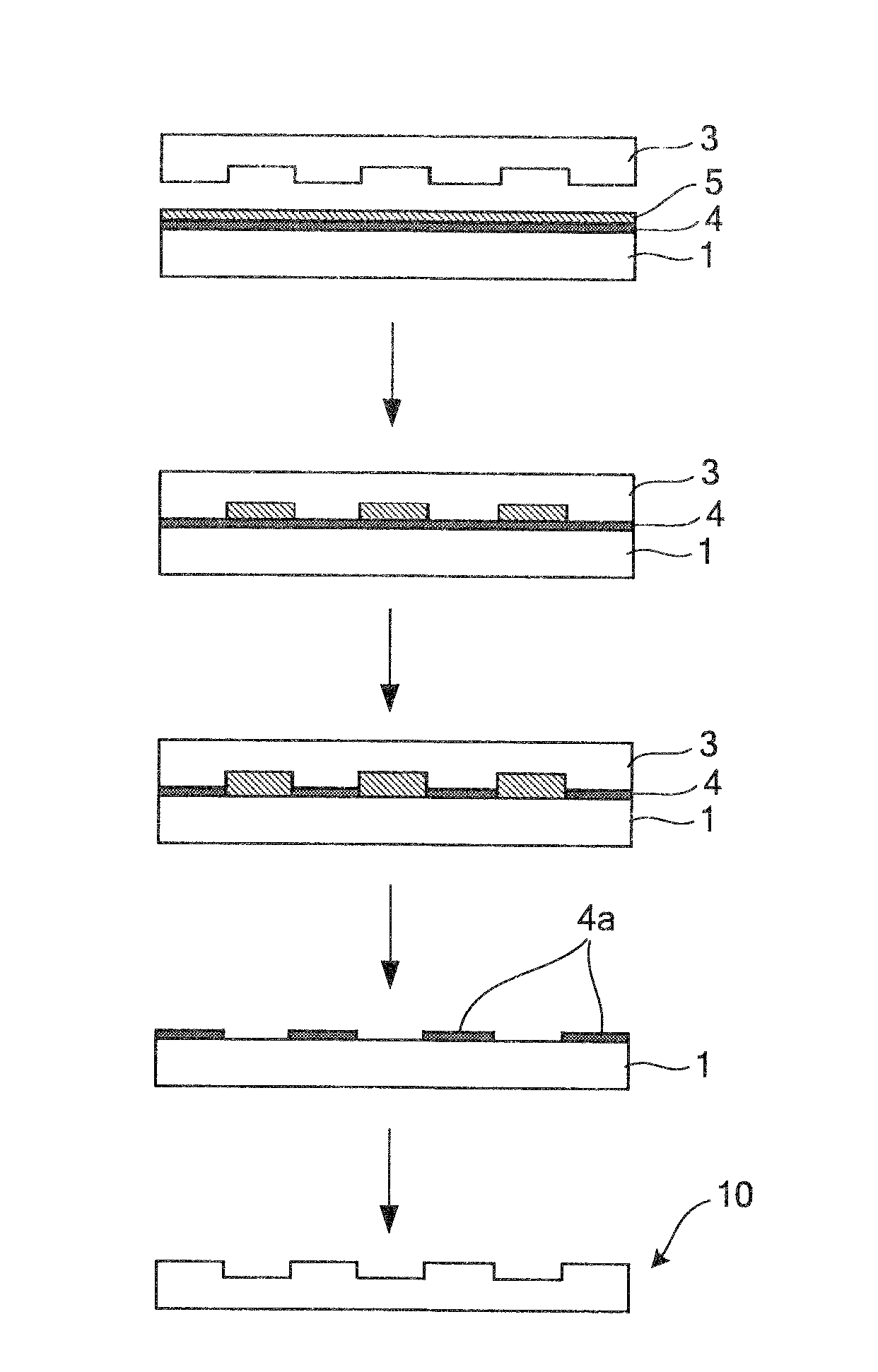
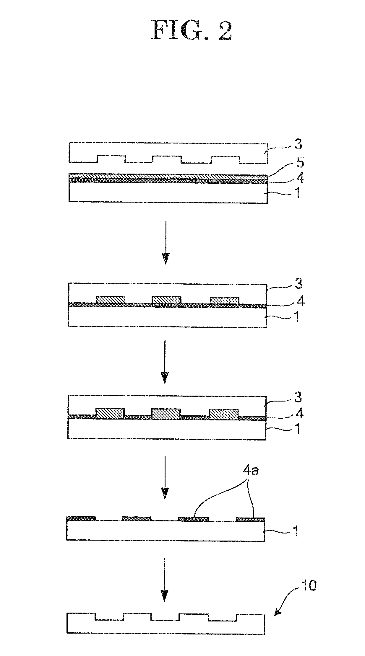
[0081]A pattern was formed and a mold structure was produced by replication in accordance with the process shown in FIG. 2.

[0082]First of all, water was applied dropwise onto the PMMA thin film of the substrate. Then the side of the mold structure, where concave portions were provided, was pressed against the PMMA thin film and pressurized at 0.1 MPa.

[0083]Subsequently, an ultraviolet ray was applied at an irradiation intensity of 30 mW / cm2 for 3 minutes, using a low-pressure mercury vapor lamp, so as to pass through the mold structure.

[0084]Next, after the application of the ultraviolet ray, the substrate and the mold structure were separated from each other. Here, ...

example 2

—Formation of a Pattern and Production of a Mold Structure by Replication—

[0088]Example 2 was carried out in a manner similar to Example 1, except that hydrogen peroxide was used as an active species supply source instead of water. An ultraviolet ray was applied at an irradiation intensity of 30 mW / cm2 for 1 minute, using a low-pressure mercury vapor lamp. Consequently, since hydrogen peroxide is higher than water in oxidative decomposition rate, a PMMA thin film pattern, i.e. the PMMA thin film from which parts in positions corresponding to concave portions of the mold structure had been removed by oxidative decomposition, was formed on the substrate as in Example 1 even though the length of time of the etching had been shortened.

[0089]Subsequently, with the obtained PMMA thin film pattern serving as a mask, the substrate was dry-etched (subjected to ashing to remove a residual film, and then RIE with a fluorine-based gas) such that hollows having a predetermined depth were formed ...


PUM

PropertyMeasurementUnit
wavelengthaaaaaaaaaa
thicknessaaaaaaaaaa

Abstract

To provide a pattern forming method including: providing an active species supply source to at least one of a mold structure having a plurality of concave portions in its surface, and an object to be patterned; pressing the side of the mold structure, where the concave portions are provided, against the object so as to encapsulate the active species supply source in the concave portions; and oxidatively decomposing parts of the object which are in positions corresponding to the concave portions, by irradiating the active species supply source with excitation light through one of the mold structure and the object.

Description

BACKGROUND OF THE INVENTION[0001]1. Field of the Invention[0002]The present invention relates to a pattern forming method, a substrate processing method and a mold structure replication method which enable a mold structure to be highly accurately and efficiently replicated without reversing a pattern.[0003]2. Description of the Related Art[0004]In a conventional nanoimprinting method, as shown in FIG. 1, a mold structure 3 having a concavo-convex pattern on its surface is pressed against a resin layer 2 formed on a substrate 1, and the concavo-convex pattern of the mold structure 3 is thus transferred into the resin layer 2. Subsequently, the substrate 1 is etched while convex portions formed in the resin layer serve as a mask. A structure (mold structure) 10 obtained has a transferred pattern which is an inversion of the pattern of the mold structure 3. Japanese Patent Application Laid-Open (JP-A) No. 2007-73712, for example, proposes an anodic oxidation patterning method using a c...

Claims


Application Information

Patent Timeline
Patent Type & Authority Patents(United States)
IPC IPC(8): B44C1/22
CPCB82Y10/00B82Y40/00G03F7/0002
Inventor WAKAMATSU, SATOSHI
Owner FUJIFILM CORP
Why Eureka
Try Eureka