Universal joint arrangement

a universal joint and joint technology, applied in the direction of shafts and bearings, rotary combination bearings, rotary bearings, etc., can solve the problems of uneven radial pressure distribution, unfavorable load application, and joint yoke elastic deformation, and achieve low number of components, eliminate negative influences of torque transferring components, and simple structure

Active Publication Date: 2013-02-26
VOITH PATENT GMBH
View PDF9 Cites 0 Cited by
  • Summary
  • Abstract
  • Description
  • Claims
  • Application Information

AI Technical Summary

Benefits of technology

[0007]The invention is therefore based on the object of further developing a bearing system for universal joint arrangements of the initially named type, in particular for use in heavy propeller shafts in such a way that the named disadvantages can be prevented, i.e. said system exhibits a simple structure as well as a low number of components. The elimination of the negative influences in deformation of the torque transferring components to the bearing arrangement, in particular the axial bearing is to be achieved in the process independently from concrete types of load with the most standardized possible solution. The universal joint arrangement, in particular the bearing system and its individual elements should stand out in the process due to a low design and manufacturing expenditure as well as low costs.

Problems solved by technology

The problem of such a bearing arrangement lies in the fact that in the case of anti-friction suspension the individual anti-friction bearings, along with a high base torque, are additionally loaded by high torque impacts and simultaneous transversal accelerations, in particular in the case of use in rolling mill drives.
These loads lead to elastic deformations of the joint yoke both in the region of the flange as well as also within the eye of the yoke.
These influences due to operation as well as design result in misalignments with an unfavorable load application in the bearing, namely a mismatch of the bore of the yoke, inclined position of the bore, spring deflection of the journal as well as a radial clearance in the radial bearing and the spring deflection of the anti-friction bearing, as is disclosed in the publication G 17 57 FIG. 12.
The result is an uneven radial pressure distribution in the bearing bore, as a result of which locally high loads on the contact points of the anti-friction body of the radial bearing and excessive edge stresses arise.
If these relative movements are hindered by a too stiff bearing embedding, high constraining forces arise and with it high loads of the axial bearings, but only when the axial bearing is designed as an anti-friction bearing.
In the case of anti-friction suspension this results in too high edge stresses in one segment of the axial bearing and in lifting of the rollers in the opposing segment.
The unequal load results in a lessening of load bearing capacity.
The constructive design, in particular the layout of the individual components, is in the process always to be adapted to the possible occurring deformation travels, so that it is not possible to provide a satisfying design independently of the knowledge of these influences.
The disadvantage of this design lies in the fact that the travel is consequently not to be predefined freely, but rather must be specified via the deformation travels determined in the case of specified operational load, as a result of which a complete rubbing contact of all anti-friction elements is not given for different loads, in particular in the partial load range and the negative consequences of the design according to the state of the art cannot be completely eliminated.

Method used


Image

  • Universal joint arrangement
  • Universal joint arrangement
  • Universal joint arrangement

Examples


Embodiment Construction

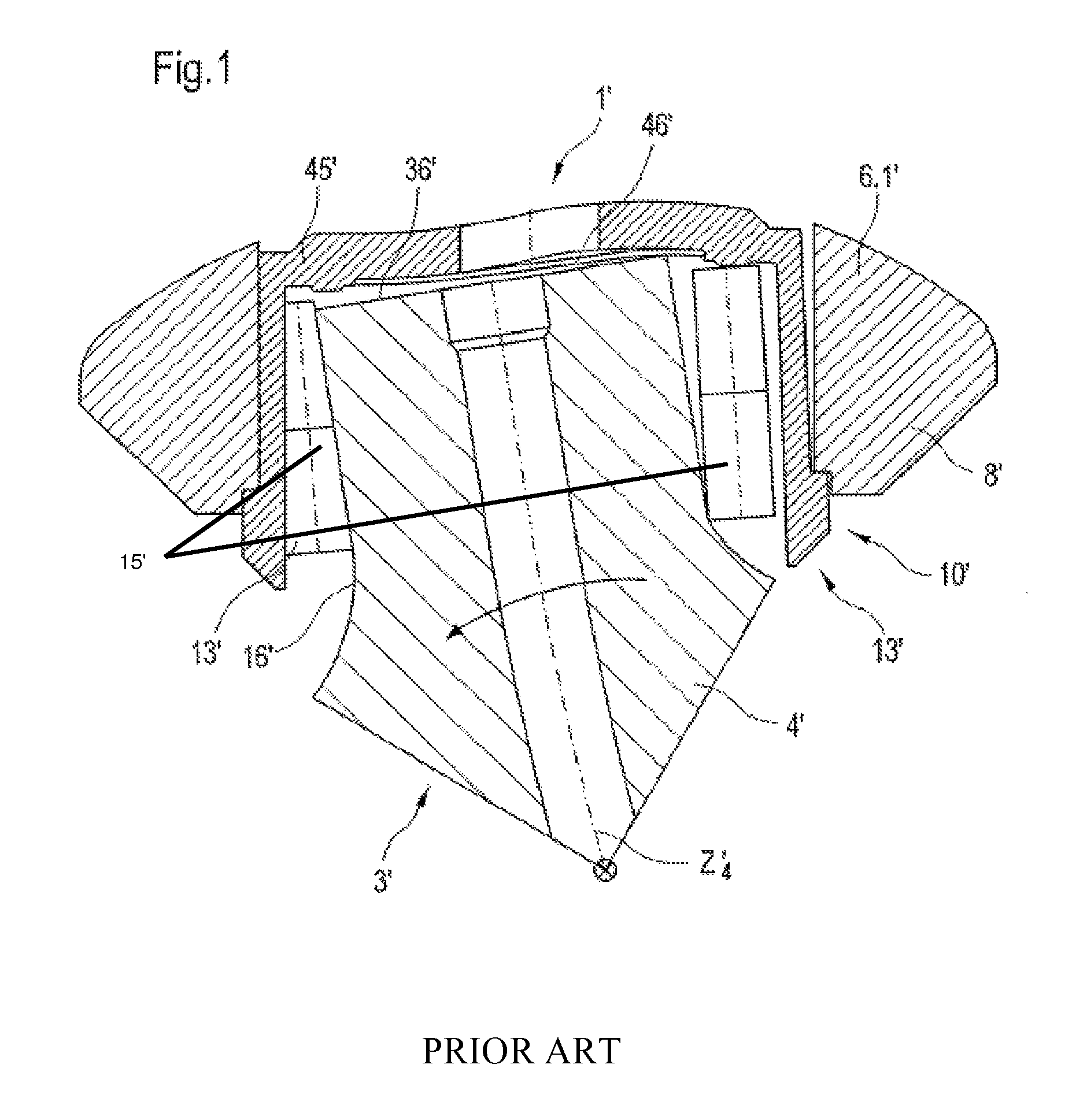
[0033]FIG. 1 illustrates in greatly exaggerated representation of the deformations of the components in a prior art universal joint system 1′, the problem underlying the solution according to the invention of the effect of relative movements in axial direction of the journal on the bearing system of a journal cross 3′ of a joint yoke 6′ with the help of a section from an axial section through the journal cross 3′. Represented in exemplary fashion is a journal 4′ having an axis Z4 which is supported by bearings via a bearing system 10′ in a joint yoke half 6.1′. Further recognizable is a bearing part 8′ of the joint yoke half 6.1′. The bearing system 10′ comprises a radial bearing 13′. In the represented case the inner bearing track of the anti-friction elements 15′ of the radial bearing 13′ is formed by the generated surface 16′ of the journal 4′. The exterior bearing surface is formed by a bearing bushing 45′. In the case of torque transfer the circumferential force causes an uneve...


PUM


Abstract

A universal joint arrangement with a journal cross, supported by bearings in two joint yokes offset to one another by 90°. Each joint yoke comprises a flange and two bearings. Each bearing has an axial bearing pressure disk that is supported by a first connection element on the joint yoke and a second connection element on the journal cross to form a first and second friction pairing. One of the connection elements has at least one elevated support region facing the axial bearing pressure disk. The support region is arranged in the region of low relative movement of the joint yoke with the journal cross, while the regions other than the support region lie in the region of greatest relative motion.

Description

[0001]This application is a divisional application of U.S. patent application Ser. No. 11 / 635,198, filed Dec. 7, 2006, now issued as U.S. Pat. No. 7,892,099, which claims priority under 35 USC §119 to German application number DE 10 2005 058 743.7, filed Dec. 8, 2005 by Voith Turbo GmbH & Co. KG.FIELD OF THE INVENTION[0002]The invention relates to a universal joint arrangement.BACKGROUND OF THE INVENTION[0003]Universal joint arrangements, in particular the bearing systems for suspension of the journal of a journal cross in joint yokes, for installation in propeller shafts are well-known in a number of designs for a multitude of application examples. Reference is made to the publication G 1757 d 08 / 02 1.000, “FEM-Simulation von Gelenkwellen mit inkompatiblen Netzen”, in which the problem of the deformations on the bearing and connection elements under load is disclosed.[0004]Embodiments of universal joint arrangements are known for joint shafts, which comprise a journal cross which i...

Claims


Application Information

Patent Timeline
Patent Type & Authority Patents(United States)
IPC IPC(8): F16D3/40
CPCF16D3/41F16D3/385F16C21/005
Inventor GRAWENHOF, PETERROSLE, HANS
Owner VOITH PATENT GMBH
Why Eureka
Try Eureka