Film formation method and method for manufacturing light-emitting element

a technology of light-emitting elements and formation methods, which is applied in the direction of instruments, diffusion transfer processes, electric/magnetic/electromagnetic heating, etc., to achieve the effect of high directivity

Inactive Publication Date: 2013-02-26
SEMICON ENERGY LAB CO LTD
View PDF34 Cites 20 Cited by
  • Summary
  • Abstract
  • Description
  • Claims
  • Application Information

AI Technical Summary

Benefits of technology

[0025]The organic material is separated with high directivity, and thus, a film of the organic material with a uniform thickness can be transferred.

Problems solved by technology

There are problems in a method for forming an EL layer by heating and transferring an organic material which is an EL material in that an edge portion of the EL layer has a small thickness and the organic material is not uniformly transferred.

Method used


Image

  • Film formation method and method for manufacturing light-emitting element
  • Film formation method and method for manufacturing light-emitting element
  • Film formation method and method for manufacturing light-emitting element

Examples


embodiment 1

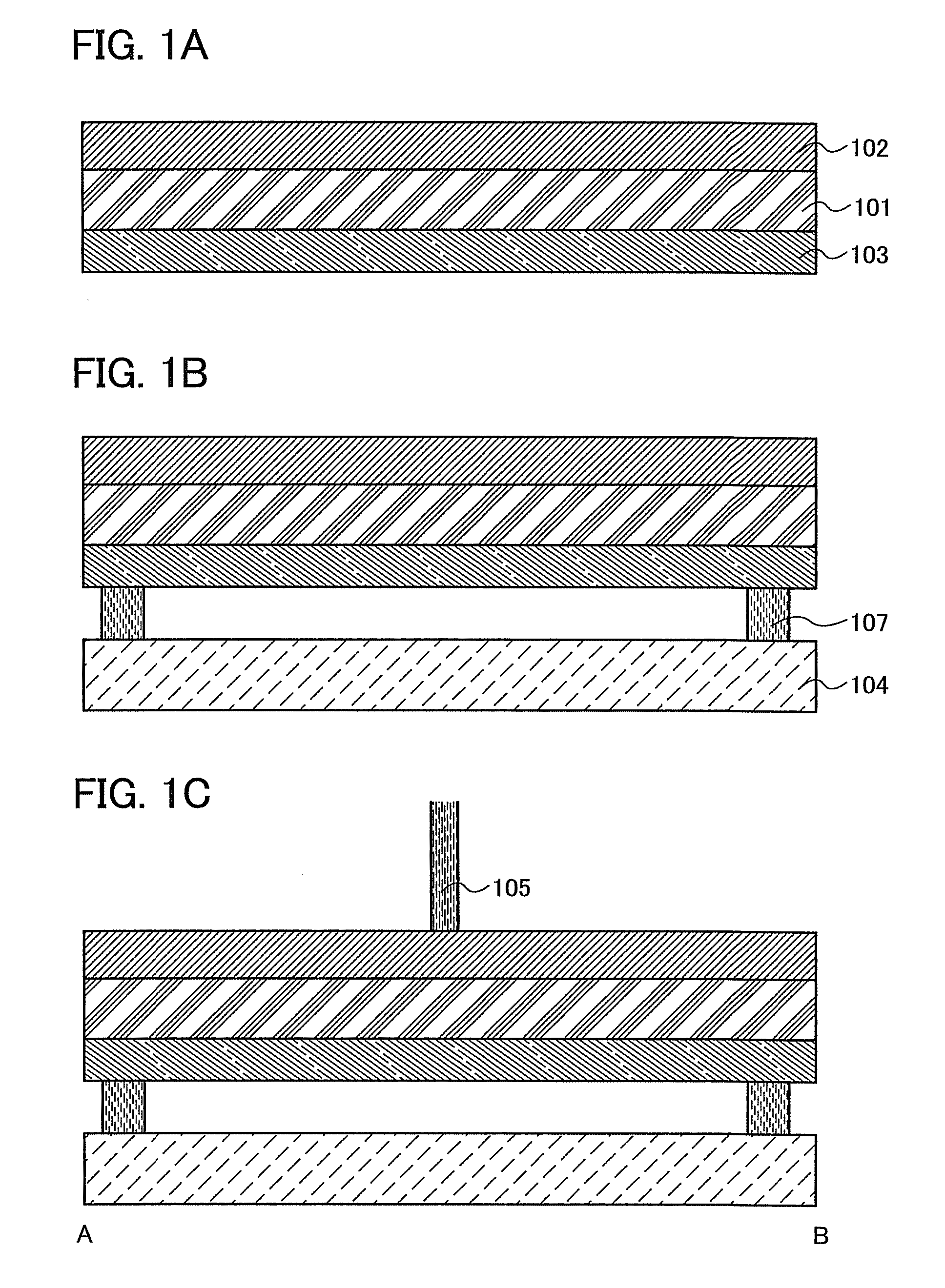
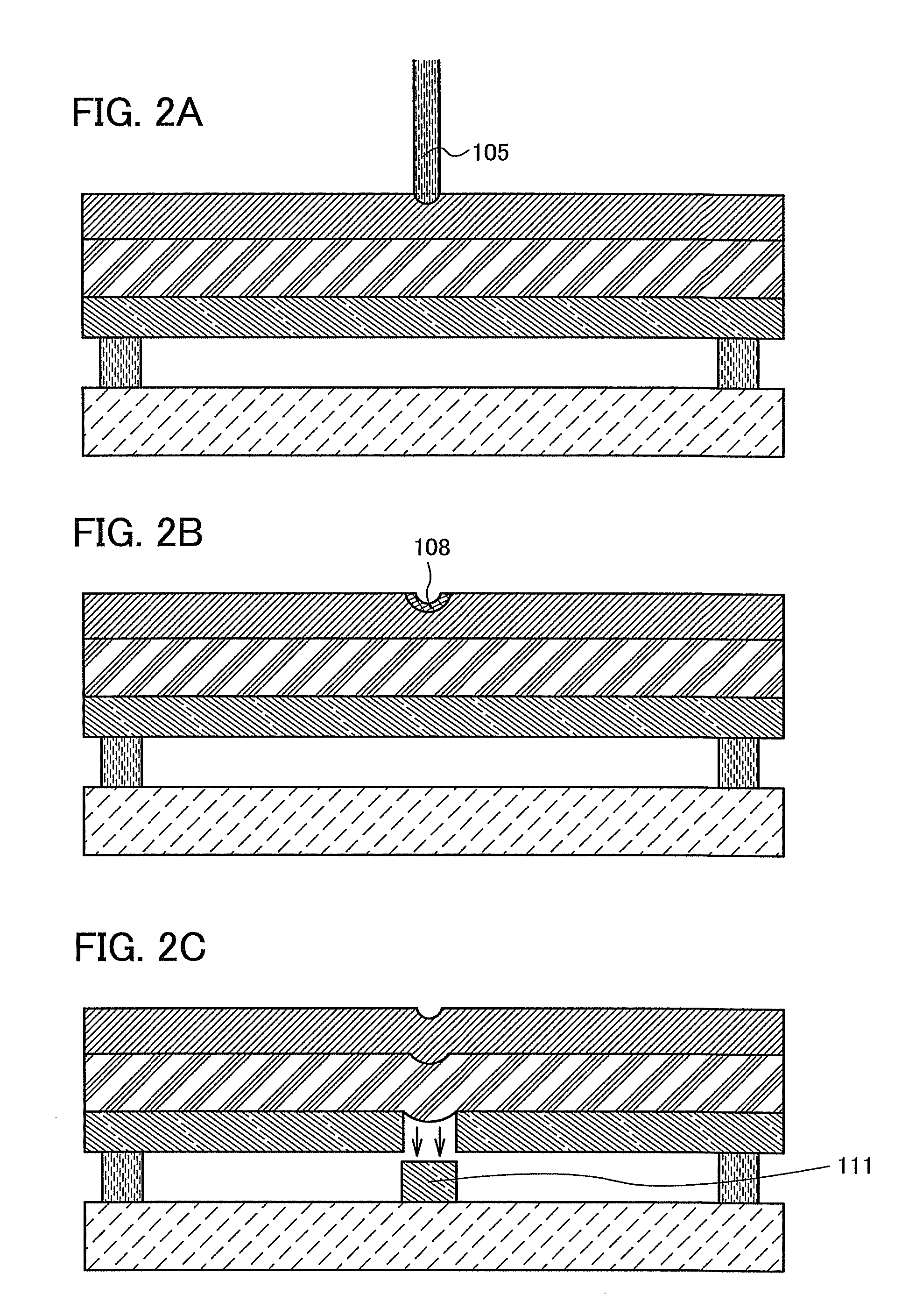
[0035]This embodiment is described with reference to FIGS. 1A to 1C, FIGS. 2A to 2C, FIG. 3, FIGS. 4A and 4B, and FIGS. 5A to 5C.

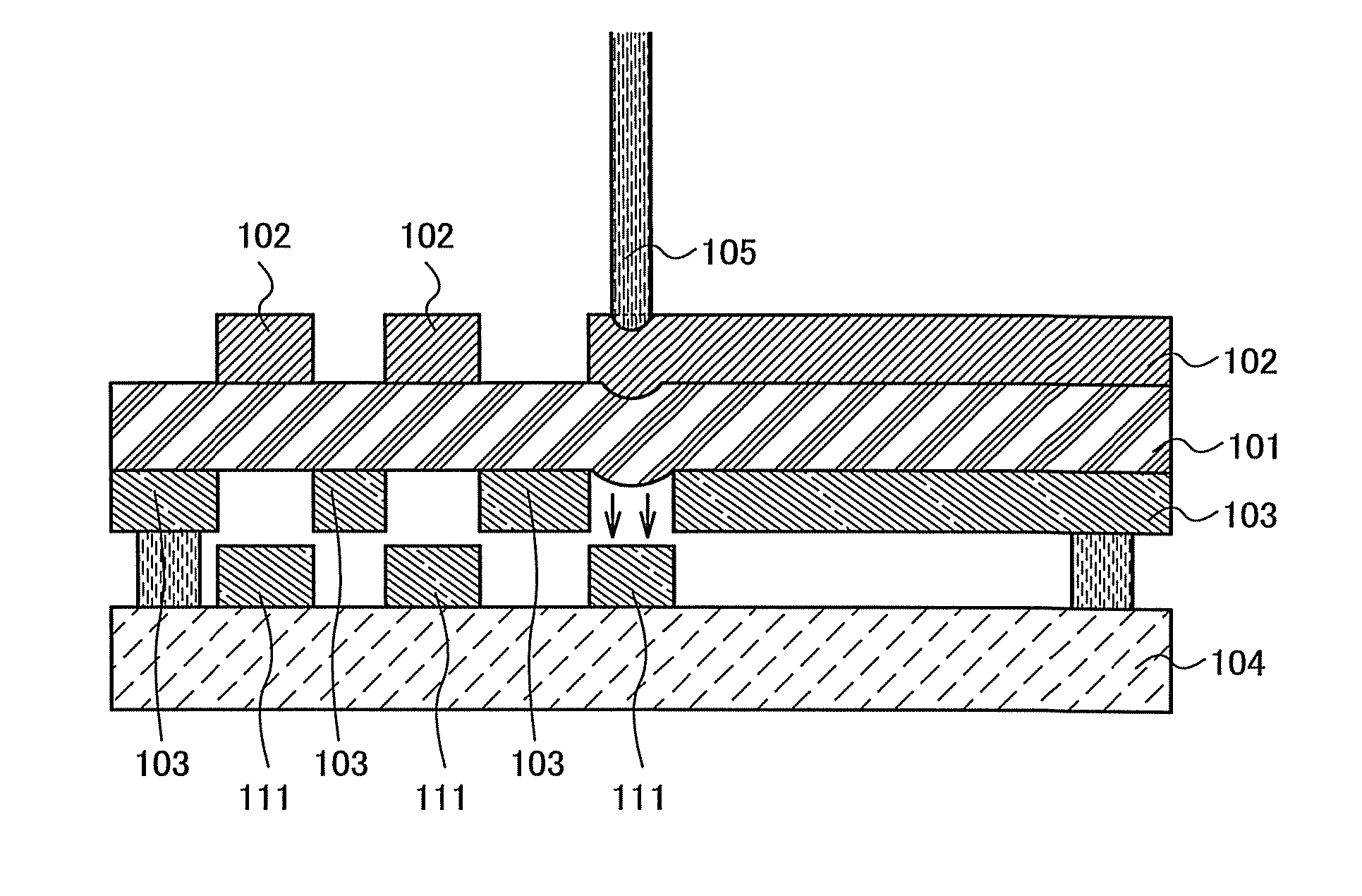
[0036]A metal film 102 is formed over an elastic substrate 101. Further, an organic material 103 is deposited onto a surface of the elastic substrate 101 which is opposite to a surface thereof where the metal film 102 is formed (see FIG. 1A). The organic material 103 is an EL material which includes at least one of a material for a light-emitting layer, a material for an electron-injecting layer, a material for an electron-transporting layer, a material for a hole-injecting layer, and a material for a hole-transporting layer. Note that a buffer layer may be provided between the elastic substrate 101 and the organic material 103. As the elastic substrate 101, a substrate which is deformed by application of external force and returns to its original shape by release of the external force is used, and in addition, a material in which a shock wave propagates i...


PUM

PropertyMeasurementUnit
thicknessaaaaaaaaaa
thicknessaaaaaaaaaa
thicknessaaaaaaaaaa

Abstract

There is a problem in a method for forming an EL layer by heating with light and transferring an organic material in that the organic material is not uniformly transferred. The present invention relates to a film formation method including the steps of forming a metal film over a first surface of an elastic substrate; forming an organic material layer onto a second surface of the elastic substrate which is opposite to the first surface; placing the second surface of the elastic substrate and a substrate on which a film is to be formed, with a space between the second surface of the elastic substrate and the substrate on which a film is to be formed; heating locally and rapidly the metal film from a first surface side of the elastic substrate to deform the elastic substrate by expansion of the metal film; and transferring the organic material layer from the elastic substrate onto the substrate on which a film is to be formed.

Description

BACKGROUND OF THE INVENTION[0001]1. Field of the Invention[0002]The present invention disclosed in the present specification relates to a film formation method and a method for manufacturing a light-emitting element.[0003]2. Description of the Related Art[0004]Light-emitting elements using an organic compound as a light emitter, which have features such as thinness, lightweight, fast response, and direct current low voltage driving, have been applied to next-generation flat panel displays.[0005]It is said that, as for a light-emitting mechanism of a light-emitting element, an EL layer (also referred to as a light-emitting layer) is sandwiched between a pair of electrodes and voltage is applied, and thus electrons injected from a cathode and holes injected from an anode are recombined in an emission center of the EL layer to form molecular excitons, and the molecular excitons release energy when returning to a ground state; thus, light is emitted.[0006]As one of methods for forming a...

Claims


Application Information

Patent Timeline
Patent Type & Authority Patents(United States)
IPC IPC(8): B05D5/06B05D5/00H05B6/00G03C8/00
CPCH01L51/0013H01L51/0037H01L51/0038H01L51/56H01L2227/323H10K71/18H10K85/114H10K85/1135H10K59/1201H10K71/40H10K71/00
Inventor TANAKA, KOICHIRO
Owner SEMICON ENERGY LAB CO LTD
Why Eureka
Try Eureka