Beta ray detector and beta ray reconstruction method

a detector and beta ray technology, applied in the field of radiation detectors, can solve the problems of abrupt decrease in detection efficiency, low energy resolution compared to inorganic scintillators, and affecting the detection efficiency of radiation, so as to increase the beta ray detection efficiency, improve the detection efficiency, and improve the effect of energy resolution

Inactive Publication Date: 2013-02-26
NAT INST OF RADIOLOGICAL SCI
View PDF10 Cites 7 Cited by
  • Summary
  • Abstract
  • Description
  • Claims
  • Application Information

AI Technical Summary

Benefits of technology

[0030]The present invention is made to solve the above-described problems. That is to say, an object of the present invention is to provide a beta ray detector and a beta ray reconstruction method capable of remarkably increasing a beta ray detection efficiency compared to that of a conventional beta ray detector and increasing the energy resolution, thereby enabling measurement of beta rays in a wide energy region.
[0031]In accordance with the present invention, a beta ray detector is provided which comprises: an absorber scintillator which is disposed to face a subject emitting beta rays and is made from an absorptive substance exhibiting a high permeability and a high rate of absorption with respect to beta rays; a backscattering scintillator which is made from a backscattering substance exhibiting a low permeability and a high rate of backscattering with respect to beta rays; and an energy detector which combines the amounts of beta ray energy absorption simultaneously measured by the two types of scintillators to reconstruct the energy and the detection position of the beta rays emitted from the subject, wherein the beta ray detector is capable of achieving consistently high detection efficiency in a wide energy region and providing high energy resolution.
[0037]Moreover, in accordance with the present invention, a beta ray reconstruction method is provided which comprises: arranging an absorber scintillator so as to face a subject emitting beta rays, the absorber scintillator being made from an absorptive substance exhibiting a high permeability and a high rate of absorption with respect to beta rays; arranging a backscattering scintillator which is made from a backscattering substance exhibiting a low permeability and a high rate of backscattering with respect to beta rays; and combining the amounts of beta ray energy absorption simultaneously measured by the two types of scintillators to reconstruct the energy and the detection position of the beta rays emitted from the subject, thereby achieving consistency in high detection efficiency in a wide energy region and providing high energy resolution.
[0044]Therefore, the amounts of energy absorption of the beta rays simultaneously measured by the two types of scintillators are combined by the energy detector, whereby most (in this example, 96%) of the beta ray energy emitted from the subject can be detected and the beta ray detection efficiency can be remarkably increased compared to that of the conventional beta ray detector.
[0045]Similarly, in a case where the backscattering scintillator is not disposed on the backside of the absorber scintillator, by combining the amounts of energy absorption of the beta rays simultaneously measured by the two types of scintillators, it is possible to detect most of the beta ray energy emitted from the subject and remarkably increase the beta ray detection efficiency compared to that of the conventional beta ray detector.
[0046]In accordance with the detector and method of the present invention, the energy resolution of the beta rays simultaneously measured by the two types of scintillators becomes an intermediate value of the resolution of a single absorber scintillator and the resolution of a single backscattering scintillator because the energy resolution corresponds to the sum of energies of both scintillators, and therefore, the energy resolution can be increased than that of the single absorber scintillator.

Problems solved by technology

For example, when an organic material (for example, a 4 mm-thick plastic) was used as a scintillator for detecting beta rays in an energy range of 0 to 3 MeV, similar to the conventional case, a detection efficiency of 90% or higher was obtained for an energy range of 0 to 1 MeV; however, there is a problem in that the detection efficiency decreases abruptly in an energy range exceeding 1 MeV and becomes 10% or lower in an energy range of 2 MeV, for example.
Moreover, an organic scintillator has a small amount of fluorescence per energy and hence has a low energy resolution compared to an inorganic scintillator.
On the other hand, when an inorganic material (for example, 4 mm-thick NaI) was used as a scintillator, there is a problem in that it is only possible to obtain a detection efficiency of less than 80% over the entire energy ranges of 0 to 3 MeV.

Method used


Image

  • Beta ray detector and beta ray reconstruction method
  • Beta ray detector and beta ray reconstruction method
  • Beta ray detector and beta ray reconstruction method

Examples


first embodiment

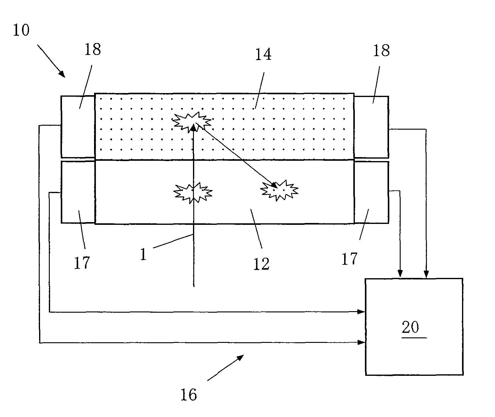
[0068]FIG. 5 is a configuration diagram illustrating a beta ray detector of the present invention.

[0069]In the drawing, a beta ray detector 10 according to the present invention is equipped with an absorber scintillator 12, a backscattering scintillator 14, and an energy detector 16.

[0070]The absorber scintillator 12 is disposed to face a subject (for example, a human body, a clothes, equipments, and the like; not illustrated) emitting beta rays 1 and is made from an absorptive substance exhibiting a high permeability and a high rate of absorption with respect to the beta rays 1. The energy region of the beta rays 1 is about 0.5 to 3 MeV, for example.

[0071]The absorptive substance exhibiting a high permeability and a high rate of absorption with respect to beta rays is an organic material, for example, and particularly preferably is an organic material having a small mass number, consisting of carbon and hydrogen molecules. A plastic scintillator or p-terphenyl is an example of the ...

second embodiment

[0128]FIG. 9 is a configuration diagram illustrating the beta ray detector of the present invention.

[0129]The exact incident positions of beta rays (fluorescence occurrence position) can be determined by the above-described fluorescence position analysis method. However, the fluorescence position analysis method cannot detect the incoming direction (the direction) of beta rays.

[0130]Therefore, in the second embodiment illustrated in FIG. 9, the absorber scintillator 12 is formed of two or more layers (in this example, three layers) of absorptive substance, and the absorption light intensity detector 17 calculates the incident positions of beta rays 1 from the light intensity distribution of the absorptive substance of each layer of the absorber scintillator 12 to detect the incoming direction thereof.

[0131]That is to say, the absorber scintillator 12 (the fluorescent screen No. 1) used in the first embodiment is arranged in multiple layers, and the mutual positions on the respective...

third embodiment

[0134]FIG. 10 is a configuration diagram illustrating the beta ray detector of the present invention.

[0135]In this example, the absorber scintillator 12 and the backscattering scintillator 14 are respectively provided on both surfaces of a flat board-like subject 4 emitting beta rays. In this drawing, the illustration of the energy detector 16 is omitted.

[0136]A phenomenon in which two beta decays occur substantially simultaneously is known as a “double beta decay.” A double beta decay where no neutrinos are emitted is a phenomenon of which the half-life is extremely long and which occurs once in about 1026 years. However, research is being conducted in various countries because observation of this decay can define or explain the neutrino mass, the Majorana particle, the CP Phase, and the like.

[0137]To measure this phenomenon, it is important to accurately measure two beta rays resulting from double beta decay. The beta ray reconstruction method of the present invention can be appli...


PUM


Abstract

A beta ray detector and a beta ray reconstruction method are capable of achieving consistently high detection efficiency of beta rays in a wider energy region compared to that of a conventional beta ray detector while enhancing energy resolution. The beta ray detector comprises an absorber scintillator disposed to face a subject emitting beta rays and that is made from an absorptive substance exhibiting a high permeability and a high rate of absorption with respect to beta rays, a backscattering scintillator disposed on the backside of the absorber scintillator and that is made from a backscattering substance exhibiting a low permeability and a high rate of backscattering with respect to beta rays, and an energy detector that combines the amounts of beta ray energy absorption simultaneously measured by the two types of scintillators to reconstruct the energy and detection position of the beta rays emitted from the subject.

Description

[0001]This is a National Phase Application in the United States of International Patent Application No. PCT / JP2007 / 068405 filed Sep. 21, 2007. The entire disclosure of the above patent application is hereby incorporated by reference.BACKGROUND OF THE INVENTION[0002]1. Technical Field of the Invention[0003]The present invention relates to a radiation detector used in the fields of, for example, nuclear facilities, nuclear medicine diagnosis, atomic physics, and the like, and more particularly, to a beta ray detector and a beta ray reconstruction method.[0004]2. Description of the Related Art[0005]In the fields of, for example, nuclear facilities, nuclear medicine diagnosis, atomic physics, and the like, a radiation detector is used for detecting or measuring alpha rays (α rays), beta rays (β rays), and gamma rays (γ rays).[0006]A radiation detector for measuring particularly gamma rays (γ rays) (the radiation detector will be hereinafter referred to as a “gamma ray detector”) is a la...

Claims


Application Information

Patent Timeline
Patent Type & Authority Patents(United States)
IPC IPC(8): G01T1/20
CPCG01T1/00G01T1/2008
Inventor NAKAMURA, HIDEHITO
Owner NAT INST OF RADIOLOGICAL SCI
Why Eureka
Try Eureka