Power converter with current vector controlled dead time

a power converter and current vector technology, applied in the field of power conversion, can solve problems such as adversely affecting the performance of a power converter, and achieve the effect of reducing harmonics and filter siz

Active Publication Date: 2013-02-26
SEMICON COMPONENTS IND LLC
View PDF15 Cites 29 Cited by
  • Summary
  • Abstract
  • Description
  • Claims
  • Application Information

AI Technical Summary

Benefits of technology

[0006]In one embodiment, a full-bridge inverter circuit with current vector controlled dead time is provided. The full-bridge inverter circuit can be used in a DC-to-AC converter system, and may reduce harmonics and filter size.
[0008]According to another embodiment of the present invention, a method is provided for a power converter system comprising a switching circuit having a plurality of switches operable to be turned on and off to cause current to flow to deliver power to a load. The method includes the following: generating PWM control signals for turning on and off the switches in the switching circuit; sensing the direction of current flow, wherein the direction of current flow is related to a likelihood of shoot-through in the switching circuit; providing a current vector signal indicative of the direction of current flow; and enabling or disabling introduction of a dead time into the PWM control signals for the switches in the switching circuit in response the current vector signal.

Problems solved by technology

If not well-controlled, full-bridge inverters can produce significant harmonics, which adversely affects the performance of a power converter.

Method used


Image

  • Power converter with current vector controlled dead time
  • Power converter with current vector controlled dead time
  • Power converter with current vector controlled dead time

Examples


Embodiment Construction

[0016]Embodiments of the present invention and their advantages are best understood by referring to FIGS. 1 through 5 of the drawings. Like numerals are used for like and corresponding parts of the various drawings.

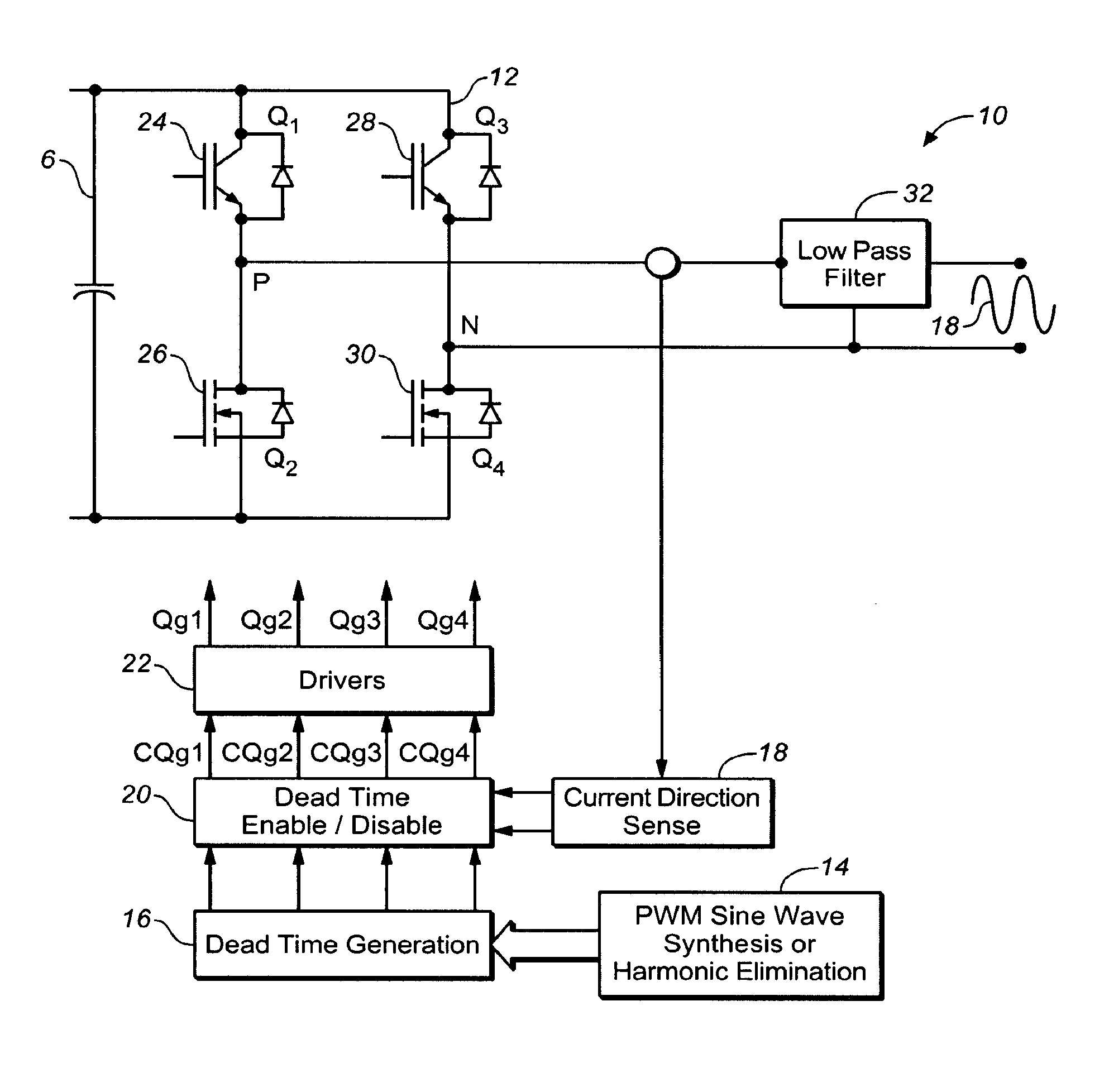
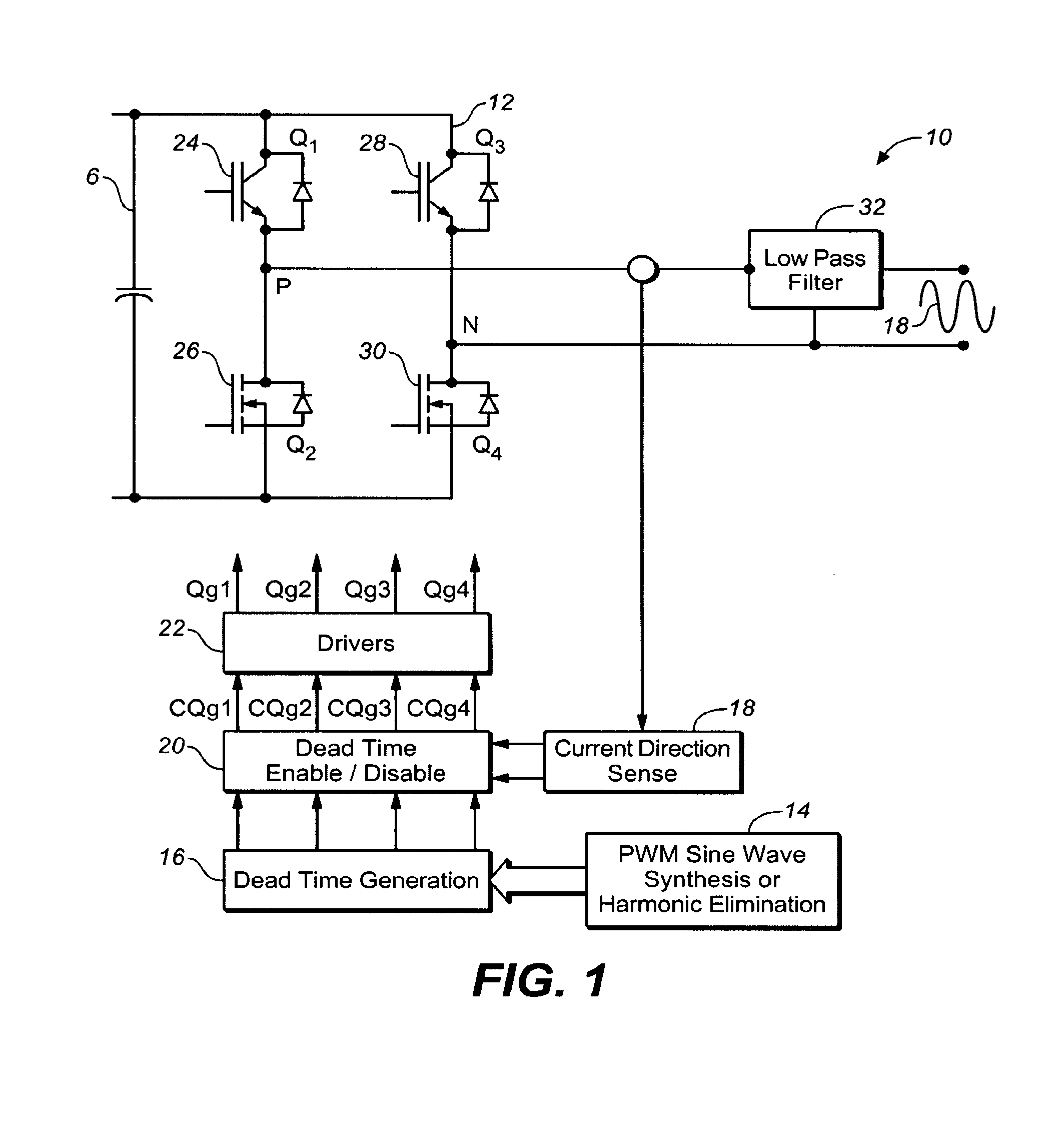
[0017]In various embodiments, the present invention provides systems and methods which enable / disable the provision of dead time for a full-bridge inverter circuit based on current vector. The full-bridge inverter circuit, which can be used in a DC-to-AC power converter system, includes a plurality of switches. The dead time (Td) may be needed to protect the switches in the full-bridge inverter circuit against different power factor loads and likelihood of short circuit or shoot-through. Dead time increases total harmonic distortion (THD) in the full-bridge inverter circuit because it reduces optimized pulse width for the switches of the circuit. Embodiments of the invention substantially reduce or eliminate the dead time when it is not needed.

[0018]Furthermore, in some e...


PUM


Abstract

In one embodiment, a method is provided for a power converter system comprising a switching circuit having a plurality of switches operable to be turned on and off to cause current to flow to deliver power to a load. The method includes the following: generating PWM control signals for turning on and off the switches in the switching circuit; sensing the direction of current flow, wherein the direction of current flow is related to a likelihood of shoot-through in the switching circuit; providing a current vector signal indicative of the direction of current flow; and enabling or disabling introduction of a dead time into the PWM control signals for the switches in the switching circuit in response the current vector signal.

Description

BACKGROUND[0001]1. Field of Invention[0002]The present invention relates to power conversion, and more particularly, to a power converter with current vector controlled dead time.[0003]2. Description of Related Art[0004]Power converters are essential for many modern electronic devices. Among other capabilities, power converters can adjust power level downward (buck converter) or adjust power level upward (boost converter). Power converters may also convert from alternating current (AC) power to direct current (DC) power, or vice versa. Power converters are typically implemented using one or more switching devices, such as transistors, which are turned on and off to deliver power to the output of the converter.[0005]One topology for a power converter system may be include a full-bridge inverter. Full-bridge inverter topology is used extensively in uninterruptible power supply (UPS) and solar power systems to convert DC power to AC power. If not well-controlled, full-bridge inverters ...

Claims


Application Information

Patent Timeline
Patent Type & Authority Patents(United States)
IPC IPC(8): H02M7/538
CPCH02M1/38H02M7/53871H02M2007/53876H02M7/5388H02M7/53876
Inventor SHEKHAWAT, SAMPAT
Owner SEMICON COMPONENTS IND LLC
Why Eureka
Try Eureka