LED lamp

a technology of led lamps and led lamps, applied in the field of lamps, can solve the problems of inherently vulnerable heat damage to solid state lighting devices, light sources still generate significant levels of heat output, and the illuminating performance of these solid state lighting devices may be severely impaired, and achieve the effect of high efficiency

Inactive Publication Date: 2013-03-05
COOLER MASTER DEVELOPMENT CORP
View PDF3 Cites 30 Cited by
  • Summary
  • Abstract
  • Description
  • Claims
  • Application Information

AI Technical Summary

Benefits of technology

[0009]One particular aspect of the instant disclosure is to provide a lamp that having a heat-dissipating structure of light weight and high efficiency, which can used as a heat-dissipating device and a housing of illuminator.

Problems solved by technology

While LEDs offer higher energy efficiency at lower operating voltage requirements, these solid state lighting devices are inherently vulnerable to heat damage.
Unfortunately, current high power LED light sources still generate significant level of heat output.
Thus, the illuminating performance of these solid state lighting devices may be severely impaired by the high temperature that results from excessive waste heat.
However, the complicated shape of the heat dissipating structure requires the employment casting construction.
Generally, casting process requires high initial cost for the molding equipments and significant level of energy consumption to preserve the molten materials in the working condition.
Moreover, products made by casting process are inevitably heavier due to the higher casting weight requirement of the fluid materials.
Furthermore, the potential porosity remained in the casted structure is inherently hazardous to the structural integrity thereof.
Moreover, stamping process may yield products that are thin and light weight.

Method used


Image

  • LED lamp
  • LED lamp
  • LED lamp

Examples


Embodiment Construction

[0023]The instant disclosure will be described more specifically with reference to the following embodiments. It is to be noted that the following descriptions of preferred embodiments are provided herein for purpose of illustration and description. It is not intended to be exhaustive or limiting to the precise form disclosed.

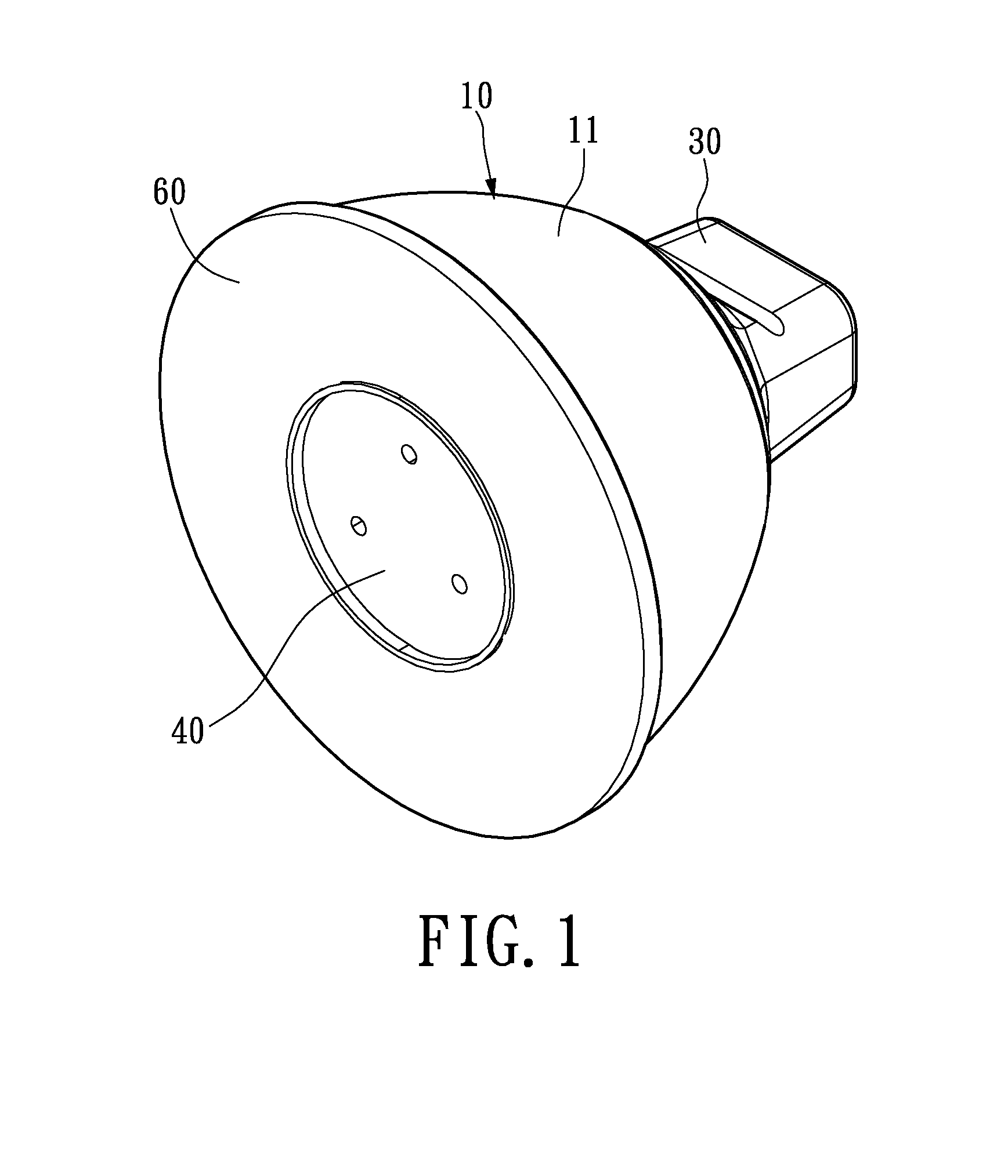
[0024]Please refer to FIGS. 1 & 7, which illustrate embodiments of LED lamps in accordance with the instant disclosure. Particularly, some external features of the exemplary lamps as shown herein resemble that of the conventional lighting devices for the purpose of maximizing compatibility and adaptability onto existing lamp housings.

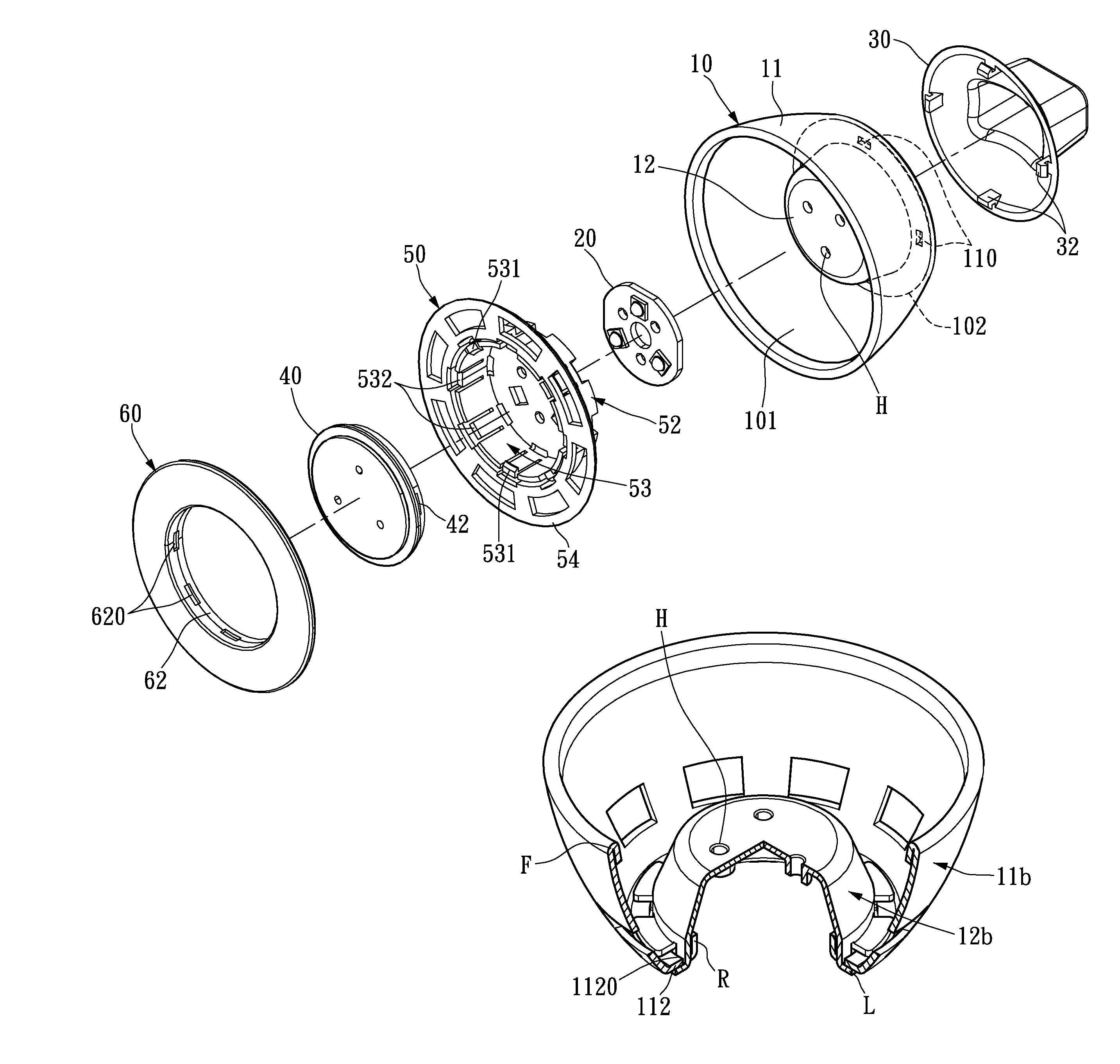
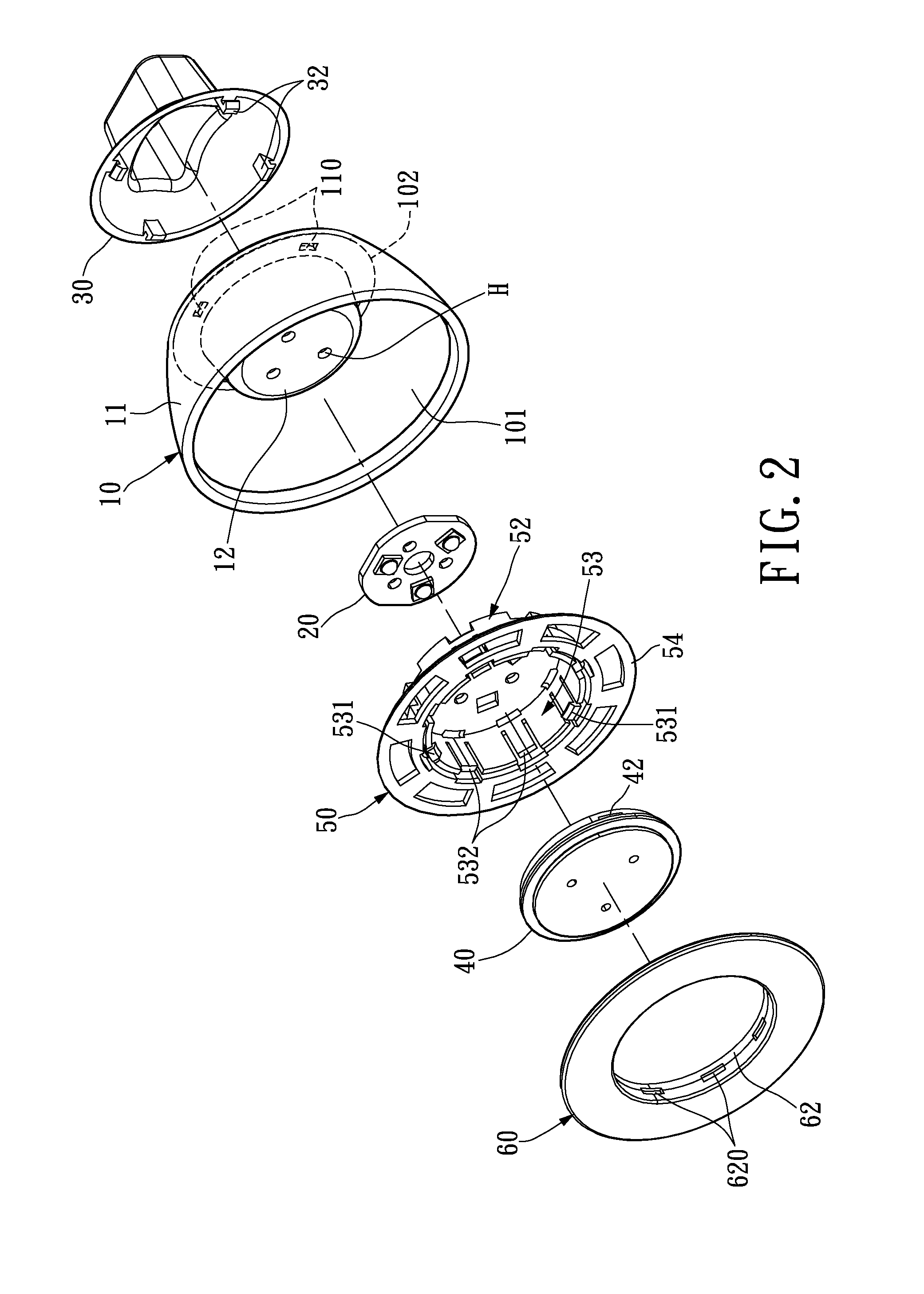
[0025]Reference is now made to FIGS. 1 and 2. Generally, the lamp includes a heat dissipating lamp shell 10, a light module 20, a connector housing 30, an optical unit 40, a holder 50 and a front cover 60. Externally, the exemplary lamp has a heat dissipating shell 10 that substantially resembles the external shape of a bowl, on wh...


PUM


Abstract

The instant disclosure relates to a lamp having a heat dissipating lamp shell particularly suitable for housing solid state light sources. The lamp comprises a lamp shell of stamping construction and a light source unit. The lamp shell comprises an outer pot portion and an inner tray portion substantially concentrically coupled to the outer pot portion. Externally, the lamp shell forms a substantial portion of the lamp. The light source unit comprises a light module disposed on the inner tray portion of the lamp shell, a controller placed at the rear portion of the lamp shell, and an electrical connecter arranged exposedly from the rear of the lamp. The lamp shell of stamping construction is beneficially characterized by the light weight and strong structural integrity, which attribute to the work hardening property of the stamping process.

Description

BACKGROUND OF THE INVENTION[0001]1. Field of the Invention[0002]The instant disclosure relates generally to a lamp having a heat dissipating lamp shell of stamping structure, and pertains particularly to a lamp that utilizes a strong light weight lamp shell of stamping structure that functions as both a heat sink and a protective housing.[0003]2. Description of Related Art[0004]Solid state light sources generally offer superior service life and energy efficiency over traditional light sources. Modern solid stage light sources, such as light emitting diodes (LEDs), are capable of generating lumen output comparable to (or even surpassing) that of the traditional light sources at only a fraction of the energy consumption. Compared to traditional lighting sources, such as incandescent or halogen lights, LED creates visible light with considerably reduced heat generation or parasitic energy dissipation. Moreover, the LED light sources are not only physically compact in size but also gene...

Claims


Application Information

Patent Timeline
Patent Type & Authority Patents(United States)
IPC IPC(8): F21V29/00
CPCF21K9/135F21K9/137F21V29/83F21V29/507F21Y2101/02F21K9/232F21K9/233F21Y2115/10
Inventor HUANG, TSUNG-CHINTSAI, CHANG HANG
Owner COOLER MASTER DEVELOPMENT CORP
Why Eureka
Try Eureka