Earth ground tester with remote control

a technology of earth ground and remote control, which is applied in the direction of testing circuits, instruments, fault locations, etc., can solve the problems of harmonic distortion, unintended path discovery, and increased equipment failure risk, so as to reduce the steps required for setting up the testing device for use, save costs, and reduce the effect of components

Active Publication Date: 2013-03-05
JOHN FLUKE MFG CO INC
View PDF10 Cites 20 Cited by
  • Summary
  • Abstract
  • Description
  • Claims
  • Application Information

AI Technical Summary

Benefits of technology

[0008]According to one aspect, the present invention provides a testing device which may be used to conduct any of the aforementioned techniques. The testing device comprises both a main unit and a remote unit adapted to communicate with one another via a communication link. After setting the testing device up according to the desired measurement technique, the respective procedure may be carried out, and the resulting measurement values are subsequently displayed on the remote unit. This allows a single operator to perform measurements while standing directly adjacent to an electrode, which is, for example, placed at a large distance from the main unit and / or other electrodes. This relieves the operator from constantly having to walk back and forth placing electrodes in different positions, and also obviates the need to return to the main unit of the testing device to consult a display and / or change parameters or settings.
[0017]In a further embodiment, either or both of the main and remote units may comprise memory storage and processing circuitry for storage and processing of all determined and measured values including, for example, distances, GPS coordinates, date and time, as well as standard test parameters. This offers the advantage that a full record of all measurements taken over a given time period or of a particular grounding system or area may be obtained which may, for example, be used for facilitated data comparison after the final measurement has been made.

Problems solved by technology

A lack of good grounding is undesirable and increases the risk of equipment failure.
The absence of an effective grounding system can lead to various problems, such as instrumentation errors, harmonic distortion issues, power factor problems and a host of possible intermittent dilemmas.
If fault currents have no path to the ground through a properly designed and maintained grounding system, they will find unintended paths.
Over time, corrosive soils with high moisture content, high salt content, and high temperatures can degrade ground rods and their connections.
So although the grounding system may have had low earth ground resistance values when initially installed, the resistance of the grounding system can increase if the ground rods, or other elements of a grounding system, corrode over time.
With present grounding test systems, in order to achieve accurate results, such tests tend to be extremely time consuming and labor intensive.
According to the prior art, all the aforementioned grounding test procedures require a considerable amount of effort walking back and forth several times between the various electrodes connected to a testing device to ensure accuracy and / or perform multiple measurements.
Specifically, once a testing device has been set up for implementing the aforementioned techniques according to the prior art, incorrect or anomalous results can occur due to inadequate contact between the electrodes and test device due to loose clips, insufficient conduction or unsuitable placement of the electrodes.
Performing this repeat measurement / correction procedure with a single operator tends to be extremely time-consuming and labor-intensive.
In order to reduce the wasted time and effort associated with this procedure, a common solution to this problem is to provide more than one operator to conduct a single test procedure; however this is often not realistic or possible due to the availability of such further personnel.
Furthermore, this solution is neither efficient nor convenient and incurs considerable extra costs.

Method used


Image

  • Earth ground tester with remote control
  • Earth ground tester with remote control
  • Earth ground tester with remote control

Examples


Embodiment Construction

[0031]It is to be understood by one of ordinary skill in the art that the present discussion is a description of exemplary embodiments only, and is not intended as limiting the broader aspects of the present invention, which broader aspects are embodied in the exemplary constructions.

Fall-of Potential Measurement

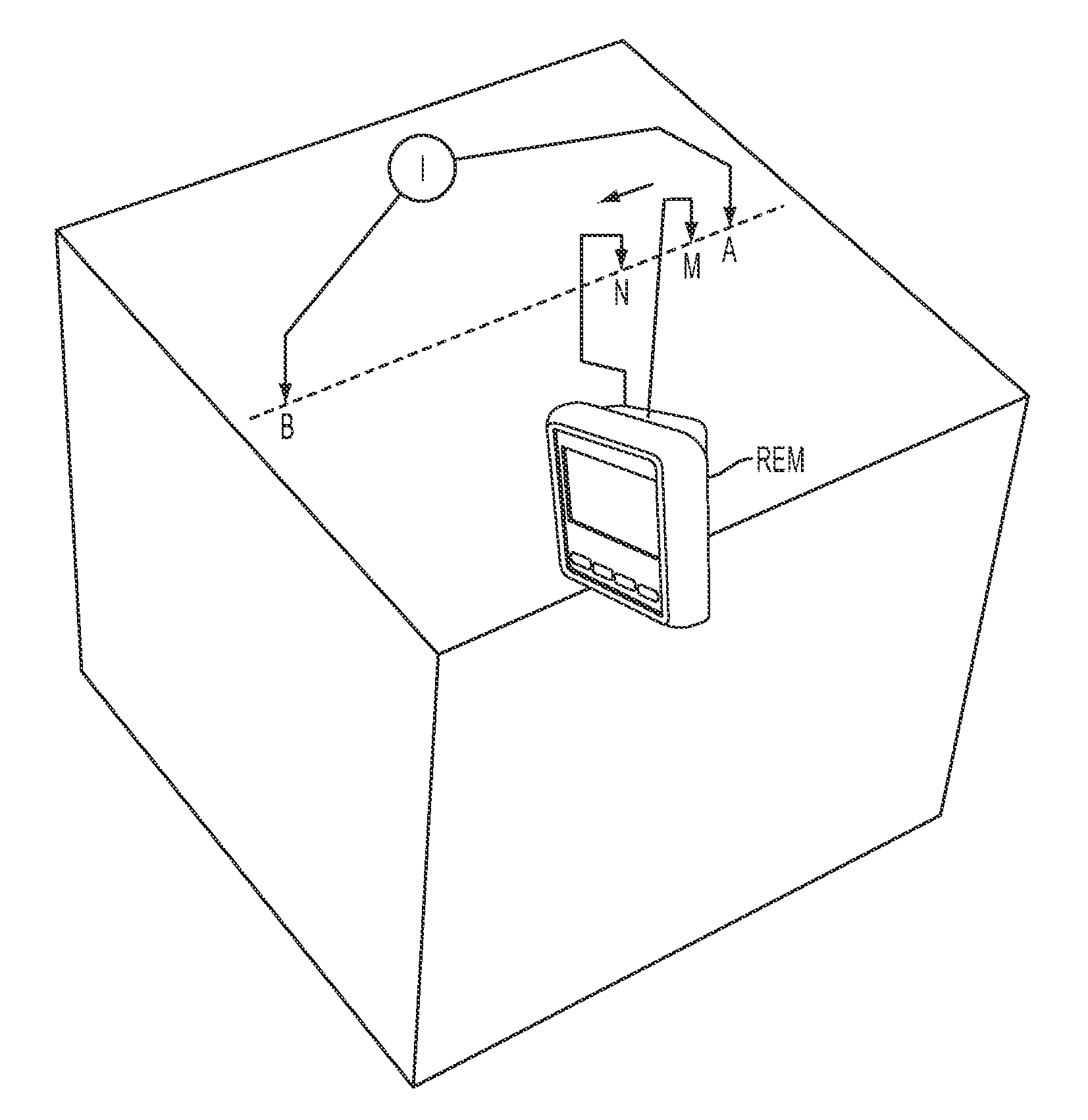
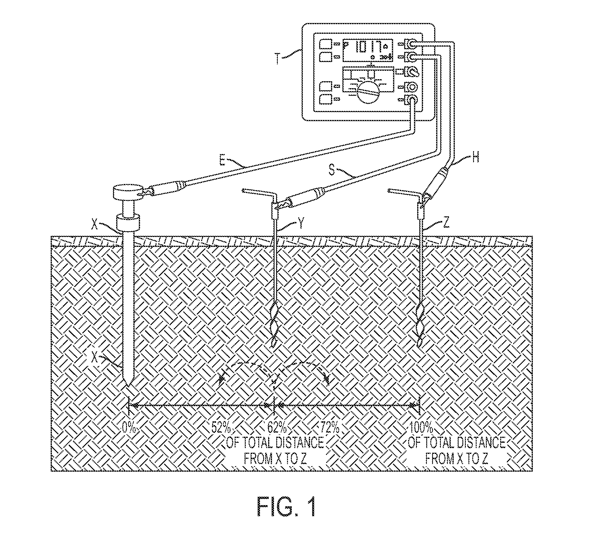
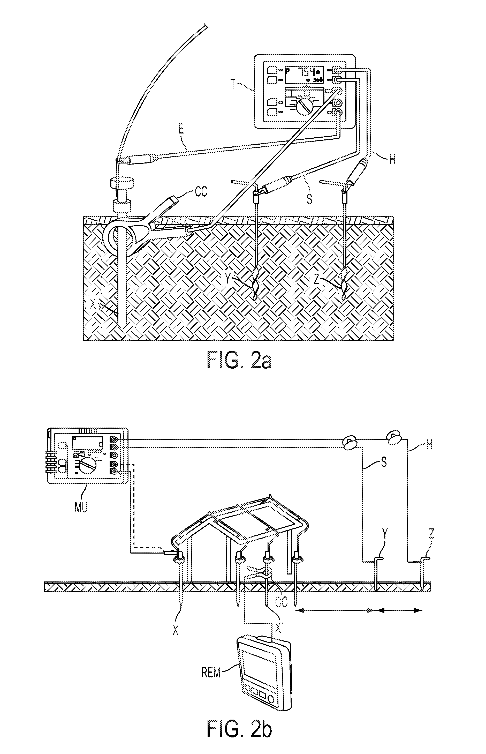
[0032]As described above, one known method of measuring the ability of an earth ground system or an individual electrode to dissipate energy from a site is the so-called “fall-of-potential” test.

[0033]In one example of this test implemented according to the present invention, an earth electrode or ground rod to be tested is disconnected from its connection to the grounding system to avoid obtaining incorrect (i.e., too low) earth resistance measurements caused by parallel grounding. The main unit of the testing device is then connected to the earth electrode X, which may then be used as a first current electrode X. One technique of performing a fall-of-potential test is thre...


PUM


Abstract

A testing device which may be used to conduct ground resistance and soil resistivity measurements. The testing device comprises both a main unit and a remote unit adapted to communicate with one another via a communication link. After setting the testing device up according to the desired measurement technique, the procedure may be carried out, and the resulting measurement values are subsequently displayed on the remote unit. This allows a single operator to perform measurements while standing directly adjacent to an electrode, which is, for example, placed at a large distance from the main unit and / or other electrodes. This relieves the operator from constantly having to walk back and forth placing electrodes in different positions, and also obviates the need to return to the main unit of the testing device to consult a display and / or change parameters or settings.

Description

FIELD OF THE INVENTION[0001]The present invention relates generally to a facilitated method and apparatus for performing multiple ground resistance and soil resistivity measurements.BACKGROUND OF THE INVENTION[0002]A lack of good grounding is undesirable and increases the risk of equipment failure. The absence of an effective grounding system can lead to various problems, such as instrumentation errors, harmonic distortion issues, power factor problems and a host of possible intermittent dilemmas. If fault currents have no path to the ground through a properly designed and maintained grounding system, they will find unintended paths. Furthermore, a good grounding system is also used to prevent damage to industrial plants and equipment and is therefore necessary in order to improve the reliability of equipment and reduce the likelihood of damage due to lightning or fault currents.[0003]Over time, corrosive soils with high moisture content, high salt content, and high temperatures can...

Claims


Application Information

Patent Timeline
Patent Type & Authority Patents(United States)
IPC IPC(8): G01R31/28G01R31/14
CPCG01V3/02G01R27/20
Inventor LAEPPLE, KLAUSKIRK, GAVINSTEUER, RONALD
Owner JOHN FLUKE MFG CO INC
Why Eureka
Try Eureka