Actuator, optical scanner and image forming device
a technology of optical scanner and image forming device, which is applied in piezoelectric/electrostrictive/magnetostrictive devices, microelectromechanical systems, instruments, etc., can solve the problems of difficult to perform a desired scanning characteristic, the light reflected by the reflection mirror cannot be scanned to a desired position of an object, and the inability to achieve desired rotation characteristics. , to achieve the effect of reducing or eliminating influences, and a larger rotation
- Summary
- Abstract
- Description
- Claims
- Application Information
AI Technical Summary
Benefits of technology
Problems solved by technology
Method used
Image
Examples
first embodiment
[0045]A first embodiment of the actuator will be described.
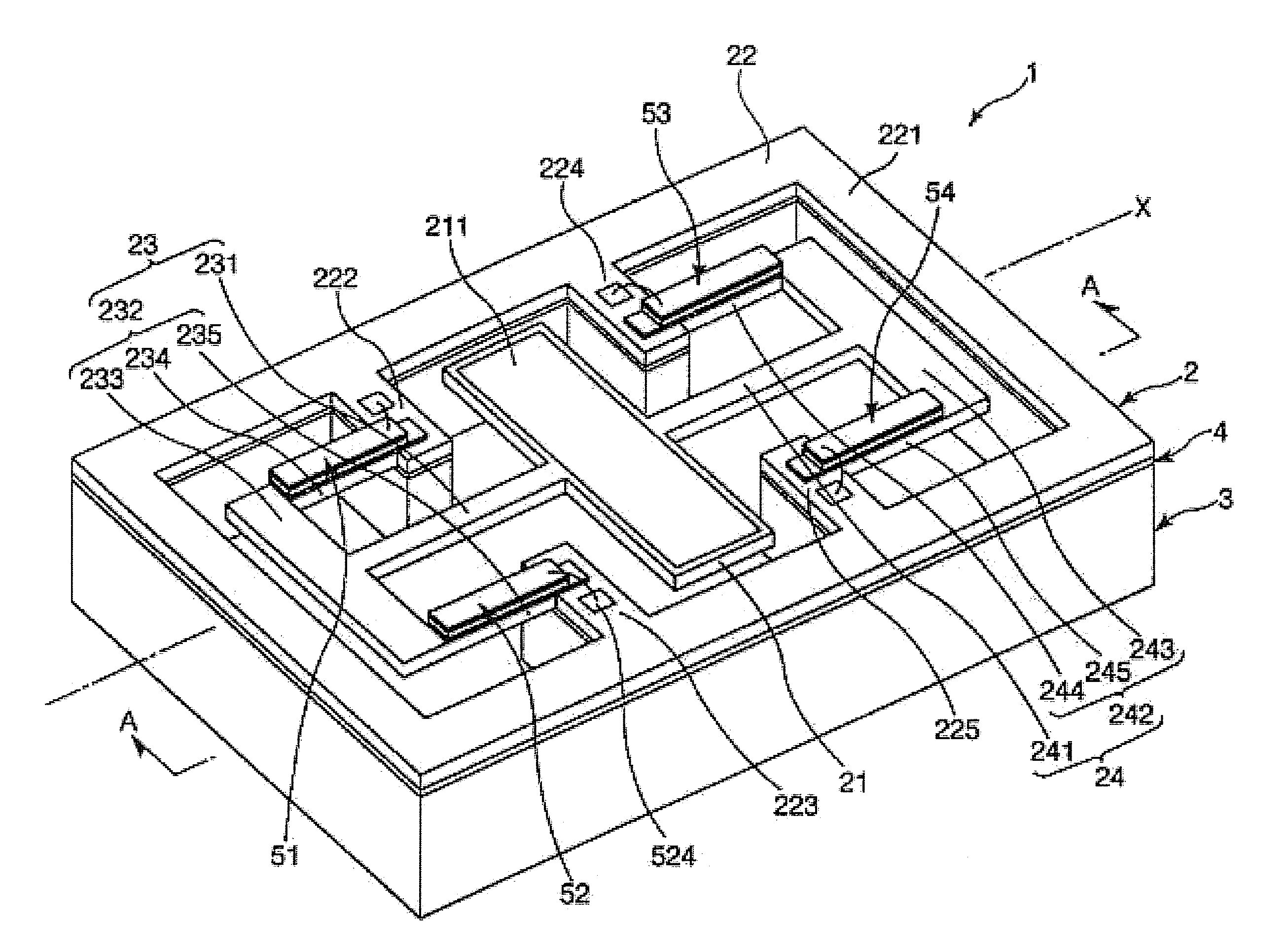
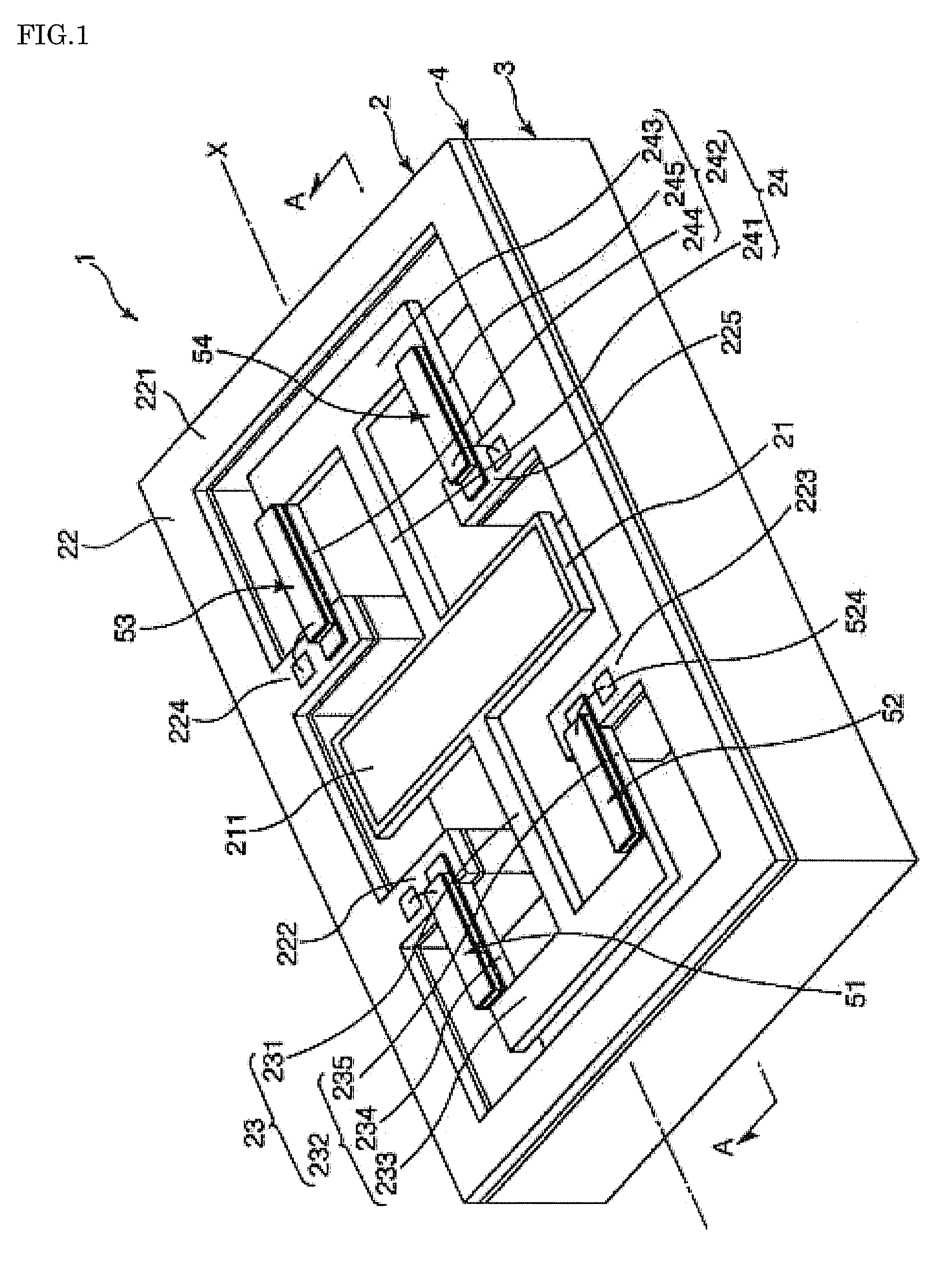
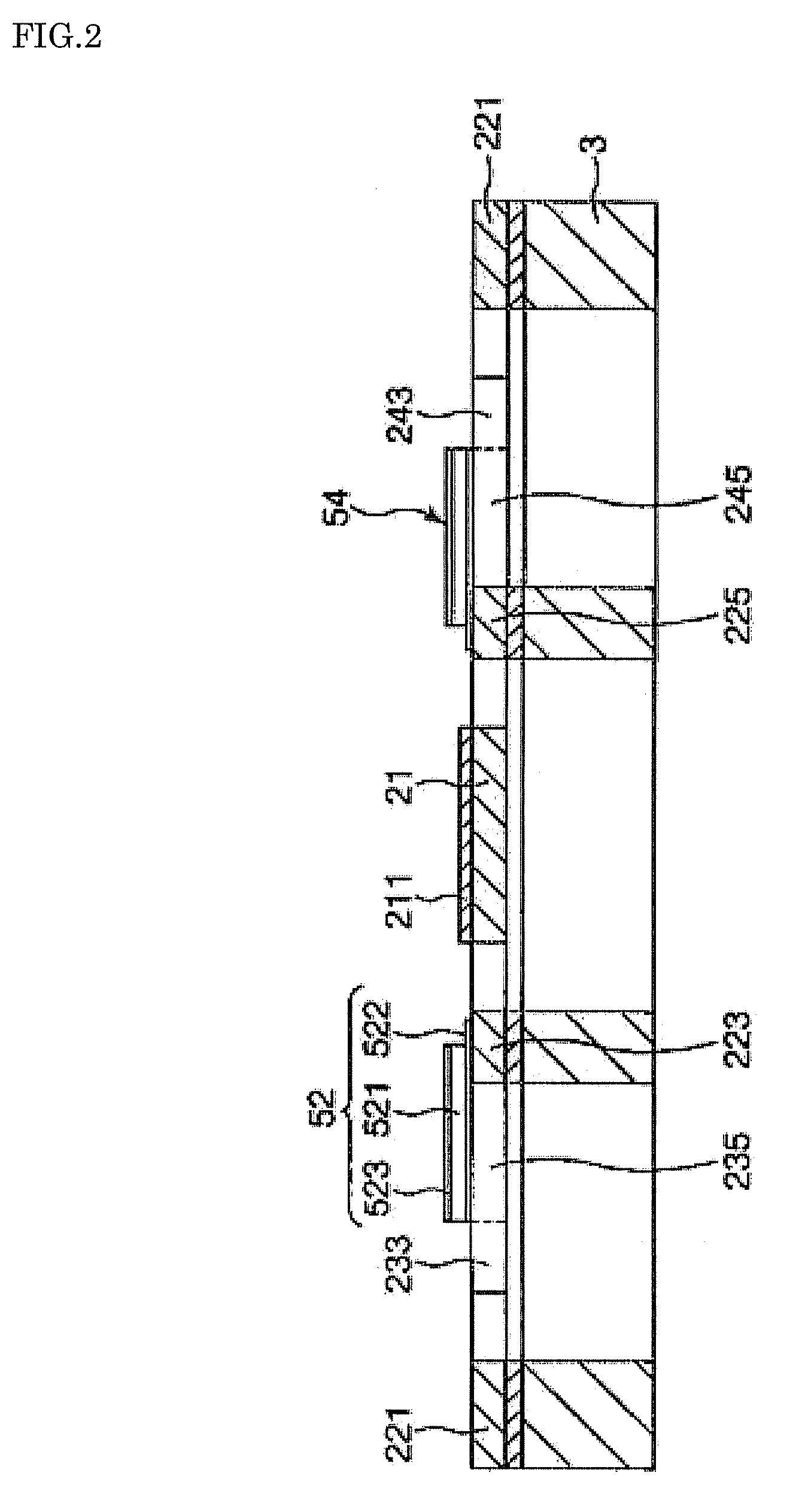
[0046]FIG. 1 is a perspective view of the actuator of the first embodiment. FIG. 2 is a sectional view taken along the line A-A in FIG. 1. FIGS. 3A and 3B show an example of a waveform of voltage applied to a piezoelectric element included in the actuator shown in FIG. 1. For expository convenience, the front side, the rear side, the right side, and the left side in FIG. 1 are described as “up,”“down or low,”“right,” and “left” respectively. Likewise, the top side, the bottom side, the right side, and the left side in FIG. 2 are described as “up,”“down or low,”“right,” and “left” respectively.
[0047]An actuator 1 includes a base 2 having a two-degree of freedom vibration system as shown in FIG. 1, and a support substrate 3 supporting the base 2 with a bonding layer 4 interposed therebetween.
[0048]The base 2 is provided with a movable plate 21, a supporter 22 to support the movable plate 21, a pair of linking portions 23 and 2...
second embodiment
[0107]Next, an actuator according to a second embodiment of the invention will be described.
[0108]FIG. 4 is a top view illustrating the actuator of the second embodiment. FIG. 5 is a sectional view taken along the line B-B in FIG. 4. For expository convenience, the top side in FIG. 5 is described as “up,” while the bottom side is described as “down or low.”
[0109]The following description of an actuator 1A of the second embodiment focuses primarily on differences from the actuator 1 of the first embodiment, and similar points will be omitted.
[0110]The actuator 1A of the second embodiment is nearly the same as the actuator 1 of the first embodiment except for the shapes of the piezoelectric elements 51A to 54A. The same numeral is given to the same structure of the first embodiment.
[0111]Since the piezoelectric elements 51A to 54A have the same structure, only the piezoelectric element 51A will be representatively described. The description of the piezoelectric elements 52A to 54A is ...
third embodiment
[0117]Next, an actuator according to a third embodiment of the invention will be described.
[0118]FIG. 6 is a top view illustrating the actuator of the third embodiment. FIG. 7 is a sectional view taken along the line C-C in FIG. 6. FIG. 8 illustrates a piezoelectric element. FIGS. 9A and 9B illustrates an example of voltage applied to the piezoelectric element. For expository convenience, the top side in FIG. 7 is described as “up,” while the bottom side is described as “down or low.”
[0119]The following description of an actuator 1B of the third embodiment focuses primarily on differences from the actuator 1 of the first embodiment, and similar points will be omitted.
[0120]The actuator 1B of the third embodiment is nearly the same as the actuator 1 of the first embodiment except for the structures and arrangements of the piezoelectric elements 55 to 58, and the structure of the support substrate 3. The same numeral is given to the same structure of the first embodiment.
[0121]A suppo...
PUM
 Abstract
Description
Claims
Application Information
 - R&D
- Intellectual Property
- Life Sciences
- Materials
- Tech Scout
- Unparalleled Data Quality
- Higher Quality Content
- 60% Fewer Hallucinations
Browse by: Latest US Patents, China's latest patents, Technical Efficacy Thesaurus, Application Domain, Technology Topic, Popular Technical Reports.
© 2025 PatSnap. All rights reserved.Legal|Privacy policy|Modern Slavery Act Transparency Statement|Sitemap|About US| Contact US: help@patsnap.com


