Noise and vibration mitigation system for nuclear reactors employing an acoustic side branch resonator

a technology of acoustic side branch resonator and nuclear reactor, which is applied in the direction of machines/engines, nuclear elements, greenhouse gas reduction, etc., can solve the problems of degradation of steam dryers and other equipment on the bwr

Active Publication Date: 2013-03-12
WESTINGHOUSE ELECTRIC CORP
View PDF40 Cites 7 Cited by
  • Summary
  • Abstract
  • Description
  • Claims
  • Application Information

AI Technical Summary

Problems solved by technology

These acoustic standing waves create pressure fluctuations that propagate through the main steam line and cause degradation to the steam dryer and other equipment on the BWR, such as safety relief valves and turbine stop valves.

Method used


Image

  • Noise and vibration mitigation system for nuclear reactors employing an acoustic side branch resonator
  • Noise and vibration mitigation system for nuclear reactors employing an acoustic side branch resonator
  • Noise and vibration mitigation system for nuclear reactors employing an acoustic side branch resonator

Examples


Embodiment Construction

[0015]Directional phrases used herein, such as, for example and without limitation, top, bottom, left, right, upper, lower, front, back, and derivatives thereof, relate to the orientation of the elements shown in the drawings and are not limiting upon the claims unless expressly recited therein.

[0016]As employed, herein, the statement that two or more parts or components are “coupled” together shall mean that the parts are joined or operate together either directly or through one or more intermediate parts or components.

[0017]As employed herein, the statement that two or more parts or components “engage” one another shall mean that the parts exert a force against one another either directly or through one or more intermediate parts or components.

[0018]As employed herein, the term “number” shall mean one or an integer greater than one (i.e., a plurality).

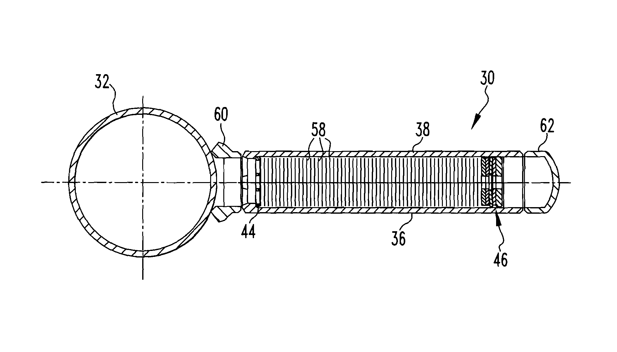
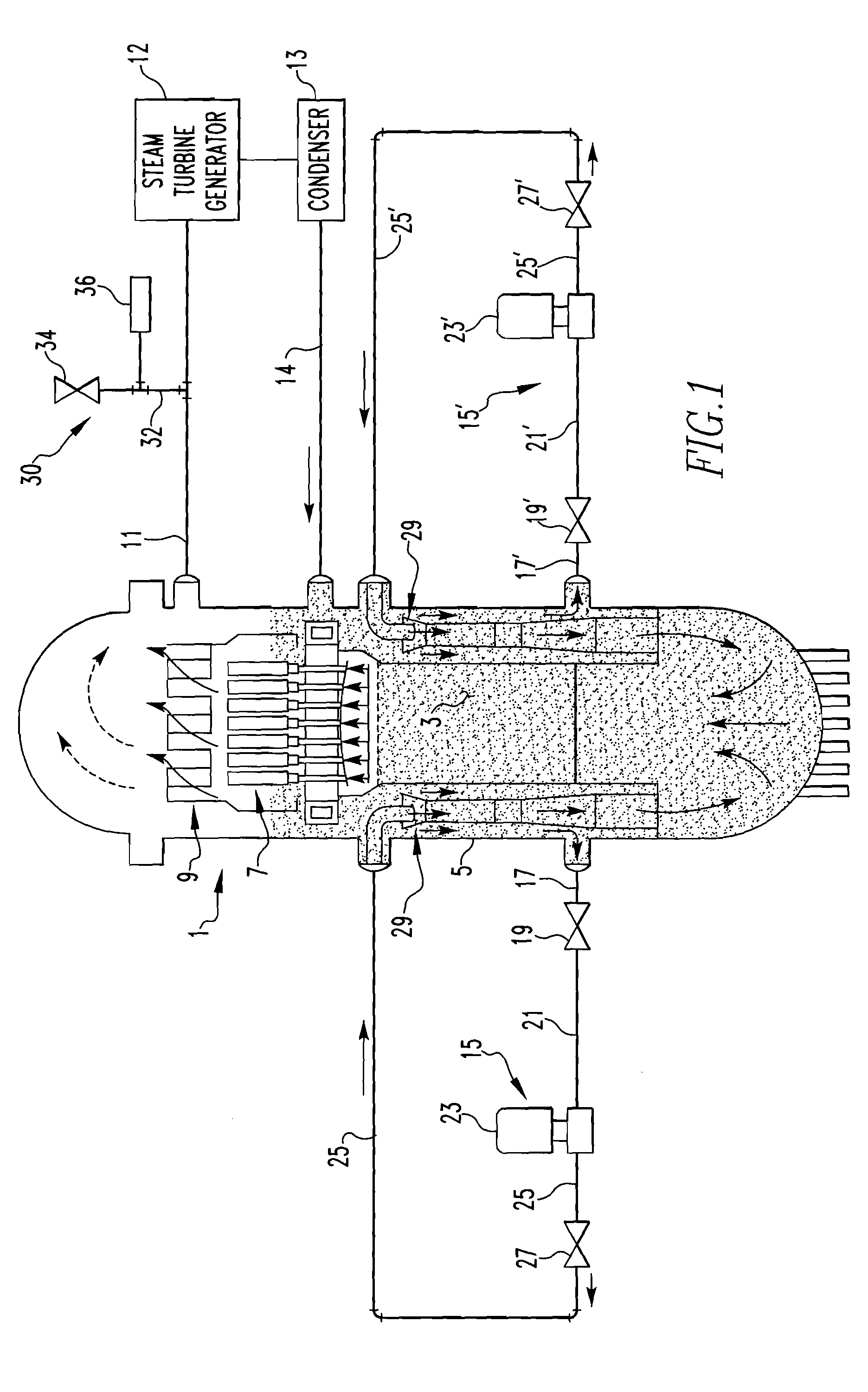
[0019]FIG. 1 is a schematic diagram of a boiling water reactor 1 in which the present invention may be implemented according to one...


PUM

PropertyMeasurementUnit
resonant frequencyaaaaaaaaaa
lengthaaaaaaaaaa
momentumaaaaaaaaaa

Abstract

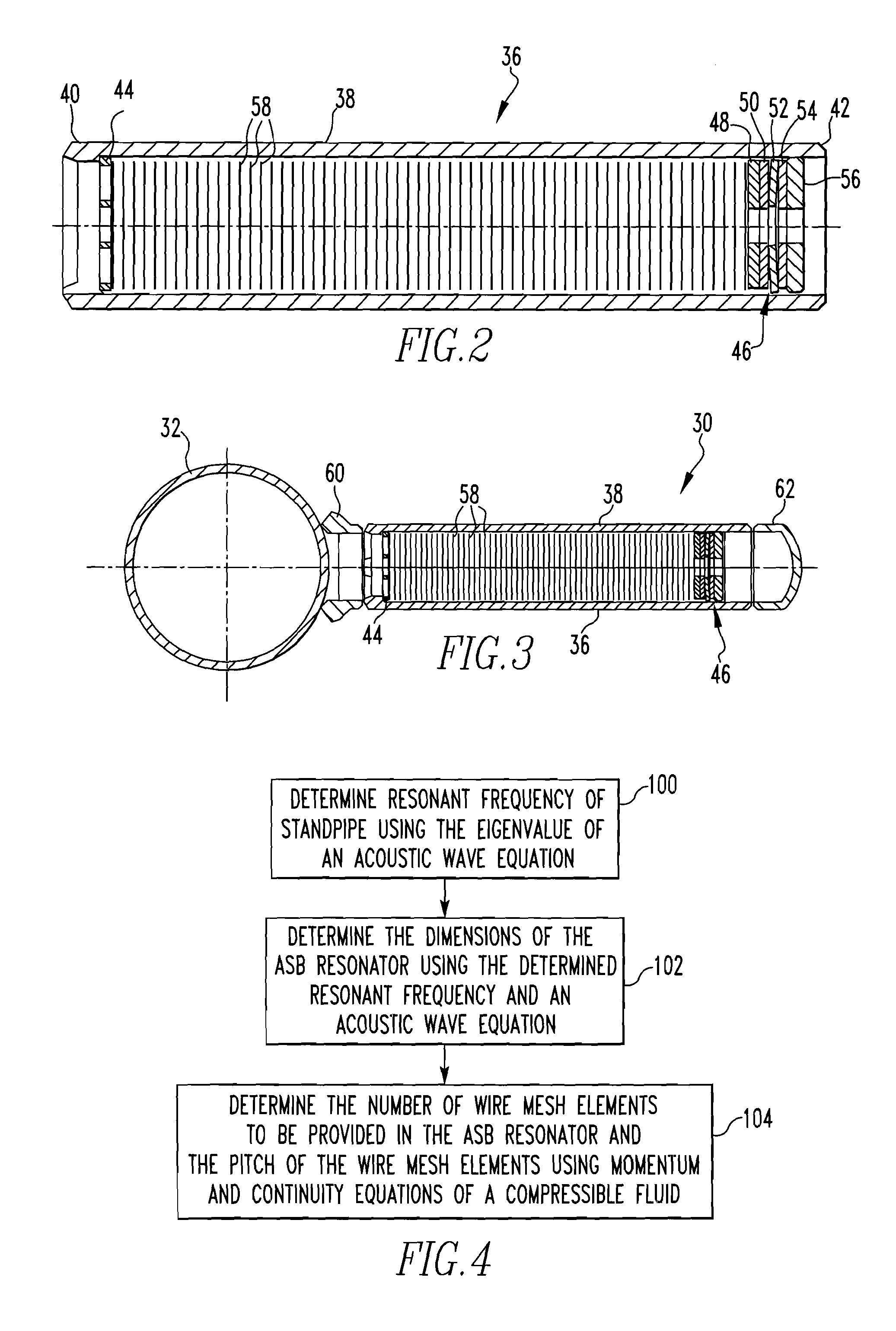
A method of designing / making an acoustic side branch resonator structured to be coupled to a standpipe of, for example, a nuclear power plant, wherein the acoustic side branch resonator includes a plurality of wire mesh elements for damping purposes. The method includes determining a resonant frequency of the standpipe, determining an active length of the acoustic side branch resonator using the resonant frequency, and determining a particular number of the wire mesh elements to be used in the acoustic side branch resonator and a pitch of each of the wire mesh elements using momentum and continuity equations of a compressible fluid.

Description

BACKGROUND OF THE INVENTION[0001]1. Field of the Invention[0002]The present invention relates to nuclear power plants, such as, without limitation, boiling water reactor (BWR) type nuclear power plants, and in particular to a system for mitigating potentially damaging noise and vibration caused by the excitation of standing waves in closed side branches of a nuclear reactor system such as a BWR system as a result of steam flowing through the main steam line of the system.[0003]2. Description of the Related Art[0004]A BWR comprises a reactor vessel partially filled with water coolant which serves as a heat transfer medium. A reactor core containing nuclear fuel that generates heat is surrounded by the water coolant. A plurality of “jet” pumps are disposed within the vessel for increasing the velocity of the coolant through the reactor core in order to efficiently remove the heat generated by the nuclear fuel in the reactor core. The heat generated by the nuclear fuel is taken-up by t...

Claims


Application Information

Patent Timeline
Patent Type & Authority Patents(United States)
IPC IPC(8): F01N1/02F01N1/08F01N1/04F01N1/00
CPCG21C17/10G21D1/00Y10T29/4978Y02E30/40F16L55/02718F16L55/052Y02E30/30Y02E30/00G21C9/00
Inventor LONGONI, GIANLUCAMUNSI, YOUNUSTHEURET, ROBERT C.FORSYTH, DAVID R.
Owner WESTINGHOUSE ELECTRIC CORP
Why Eureka
Try Eureka