Structural member

a technology of structural parts and components, applied in the field of structural parts, can solve the problems of unfavorable increase in mass and cost, and achieve the effect of high strength

Inactive Publication Date: 2013-03-12
TOYOTA JIDOSHA KK
View PDF18 Cites 9 Cited by
  • Summary
  • Abstract
  • Description
  • Claims
  • Application Information

AI Technical Summary

Benefits of technology

[0006]The present invention provides a framework member that can achieve high strength and lightweight.
[0008]This structural member includes a compression-side wall part that receives a compressive stress when the structural member is bent by receiving a load, a tension-side wall part that receives a tensile stress when the structural member is bent by receiving a load, and a coupling wall part that couples the compression-side wall part and the tension-side wall part. In this structure, the neutral axis between the compression side (contraction side) and the tension side (elongation side) of a bend is disposed in the vicinity of the compression-side wall part or disposed at the position of the compression-side wall part. Since the compressive stress field and the tensile stress field are respectively smaller and larger as the neutral axis is closer to the compression-side wall part, it is possible to reduce or eliminate the occurrence of elastic buckling due to a compressive stress. As a result, a load of up to the potential strength limit of the material can be endured on the compression side, thereby fully demonstrating the potential strength of the material. Further, since the load to be carried on the tension side can also be increased along with the improvement in proof stress on the compression side, a stress of up to the material strength limit can be produced over the entire cross section, thereby efficiently utilizing the material strength over the entire cross section. In addition, since no or almost no portion of the coupling wall part is to be in the compressive stress field, reinforcing members may be reduced in number or omitted, thereby reducing the weight and the cost. As described above, a high-strength and lightweight (low-cost) structural member can be achieved in which the neutral axis of a bend is disposed in the vicinity of the compression-side wall part.
[0009]In the structural member in accordance with the present invention, the compression-side wall part may be higher in material strength than the tension-side wall part. In this structural member, the neutral axis of a bend can be disposed in the vicinity of the compression-side wall part by increasing the material strength of the compression-side wall part compared to that of the tension-side wall part. This is because since the neutral axis is at the position where the compression-side moment (compressive stress) and the tension-side moment (tensile stress) match each other, increasing the strength (rigidity) of the compression-side wall part by increasing the material strength can accordingly reduce the distance from the neutral axis to the compression-side wall part. In addition, increasing the strength of the compression-side wall part itself can also accordingly increase the buckling strength of the compression-side wall part, thereby reducing the occurrence of elastic buckling.
[0010]In the structural member in accordance with the present invention, the compression-side wall part is preferably larger in sheet thickness than the tension-side wall part. In this structural member, the neutral axis of a bend can be disposed in the vicinity of the compression-side wall part by increasing the sheet thickness of the compression-side wall part compared to that of the tension-side wall part. In the same way as described above, increasing the strength of the compression-side wall part by increasing the sheet thickness can reduce the distance from the neutral axis to the compression-side wall part, and can increase the buckling strength of the compression-side wall part.
[0011]The present invention can provide a high-strength and lightweight structural member in which the neutral axis of a bend is disposed in the vicinity of the compression-side wall part.

Problems solved by technology

As a result, the mass and the cost are unfavorably increased.

Method used


Image

  • Structural member
  • Structural member
  • Structural member

Examples


first embodiment

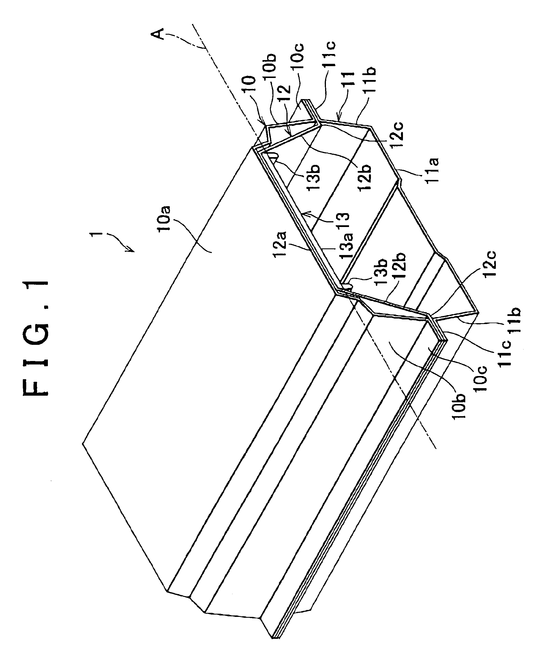
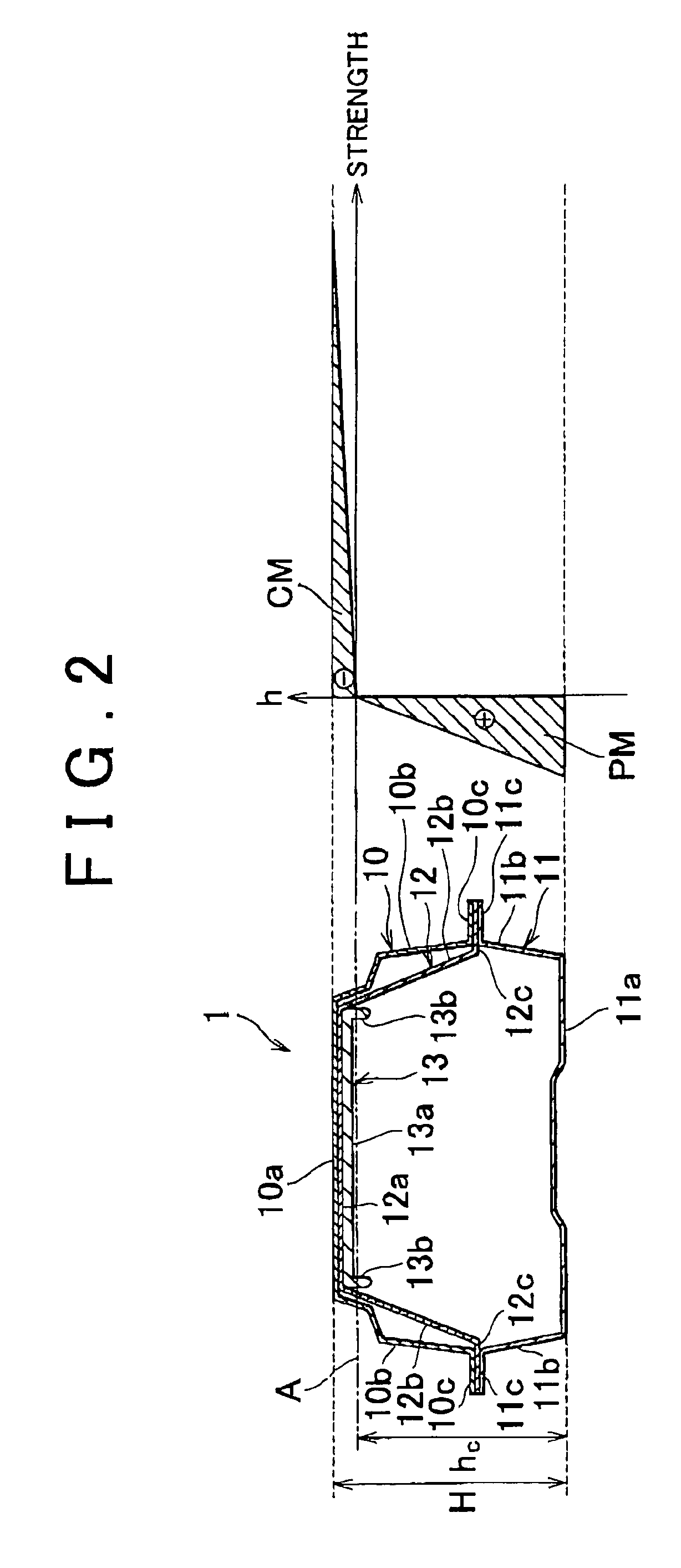
[0029]In the first embodiment, the outer wall 10a of the pillar outer panel 10, the outer wall 12a of the outer reinforcement 12, and the outer wall 13a of the hinge reinforcement 13 can be considered as the “compression-side wall part” of the present invention, the inner wall 11a of the pillar inner panel 11 can be considered as the “tension-side wall part” of the present invention, and the vertical walls 10b, 10b of the pillar outer panel 10 and the vertical walls 11b, 11b of the pillar inner panel 11 can be considered as the “coupling wall part” of the present invention.

[0030]According to the cross sectional structure of the thus configured B-pillar 1, the outer wall 10a of the pillar outer panel 10, the outer wall 12a of the outer reinforcement 12, and the outer wall 13a of the hinge reinforcement 13 (in particular, the outer wall 13a of the hinge reinforcement 13), which are to be on the compression side (contraction side) of a bend when the B-pillar 1 receives a load due to a ...

second embodiment

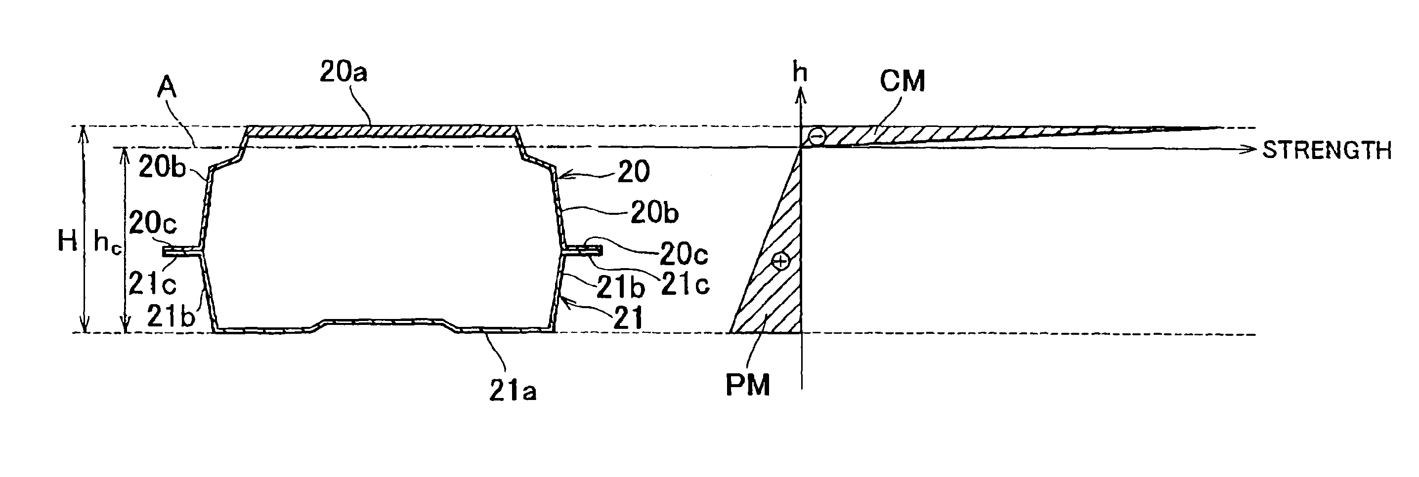
[0043]In the second embodiment, the outer wall 20a of the pillar outer panel 20 can be considered as the “compression-side wall part” of the present invention, the inner wall 21a of the pillar inner panel 21 can be considered as the “tension-side wall part” of the present invention, and the vertical walls 20b, 20b of the pillar outer panel 20 and the vertical walls 21b, 21b of the pillar inner panel 21 can be considered as the “coupling wall part” of the present invention.

[0044]According to the structure of the thus configured B-pillar 2, the outer wall 20a of the pillar outer panel 20, which is to be on the compression side of a bend when the B-pillar 2 receives a load due to a side collision or the like, has much higher strength and a much larger sheet thickness than those of the inner wall 21a of the pillar inner panel 21, which is to be on the tension side of the bend. Therefore, the stiffness (rigidity) is much higher on the compression side than on the tension side. Thus, as w...


PUM

PropertyMeasurementUnit
thicknessaaaaaaaaaa
tensile strengthaaaaaaaaaa
thicknessaaaaaaaaaa

Abstract

A structural member includes: a compression-side wall part disposed in a compressive stress field of a bend; a tension-side wall part disposed in a tensile stress field of the bend; and a coupling wall part that couples the compression-side wall part and the tension-side wall part. The neutral axis of the bend is disposed in the vicinity of the compression-side wall part. For example, the compression-side wall part is higher in material strength, and / or larger in sheet thickness, than the tension-side wall part.

Description

[0001]This is a 371 national phase application PCT / IB2008 / 002027 filed 9 May 2008, claiming priority to Japanese Patent Application No. 2007-126038 filed 10 May 2007, the contents of which are incorporated herein by reference.FIELD OF THE INVENTION[0002]The present invention relates to a structural member for application to a framework member for a vehicle or the like.BACKGROUND OF THE INVENTION[0003]When a framework member for a vehicle receives a load due to a collision or the like, it is elastically budded by a compressive stress locally on the compression side of a bend, since it is weaker on the compression side than on the tension side. Therefore, some framework members for vehicles are formed to have a closed cross sectional structure in which a reinforcement member is disposed only on the compression side of a bend (see Japanese Patent Application Publication No. 2003-731483 (JP-A-2003-231483)). FIG. 5 shows a B-pillar 100 as an example of such framework members. The B-pilla...

Claims


Application Information

Patent Timeline
Patent Type & Authority Patents(United States)
IPC IPC(8): B62D25/04
CPCB23K26/24B62D21/157B62D25/04B23K2201/185B23K2101/185
Inventor MORI, TAKEO
Owner TOYOTA JIDOSHA KK
Why Eureka
Try Eureka