Method and system for surface water treatment

a surface water treatment and system technology, applied in water cleaning, filtration separation, separation processes, etc., can solve the problems of insufficient treatment, contaminated surface water in the world, and no reliable means to remove nitrogen-containing compounds from surface water

Active Publication Date: 2013-03-12
RITTMANN BRUCE E
View PDF10 Cites 1 Cited by
  • Summary
  • Abstract
  • Description
  • Claims
  • Application Information

AI Technical Summary

Problems solved by technology

Surface waters throughout the world are contaminated with nutrients that come from a range of non-point sources (e.g., agricultural and storm water run-off, high-density animal operations, and atmospheric deposition), and inadequately treated wastewaters.
Up to the present time, no reliable means is available to remove these nitrogen-containing compounds from surface water once the water is contaminated from one or more of the sources.
Limited removal is possible when the water passes through natural or engineered wetlands, but normally these systems are able to remove only a modest fraction of the total nitrogen load in the surface water.
The methods and apparatus disclosed in the references mentioned above are not suited for treatment of contaminated water in an open body of water.

Method used


Image

  • Method and system for surface water treatment
  • Method and system for surface water treatment
  • Method and system for surface water treatment

Examples


Embodiment Construction

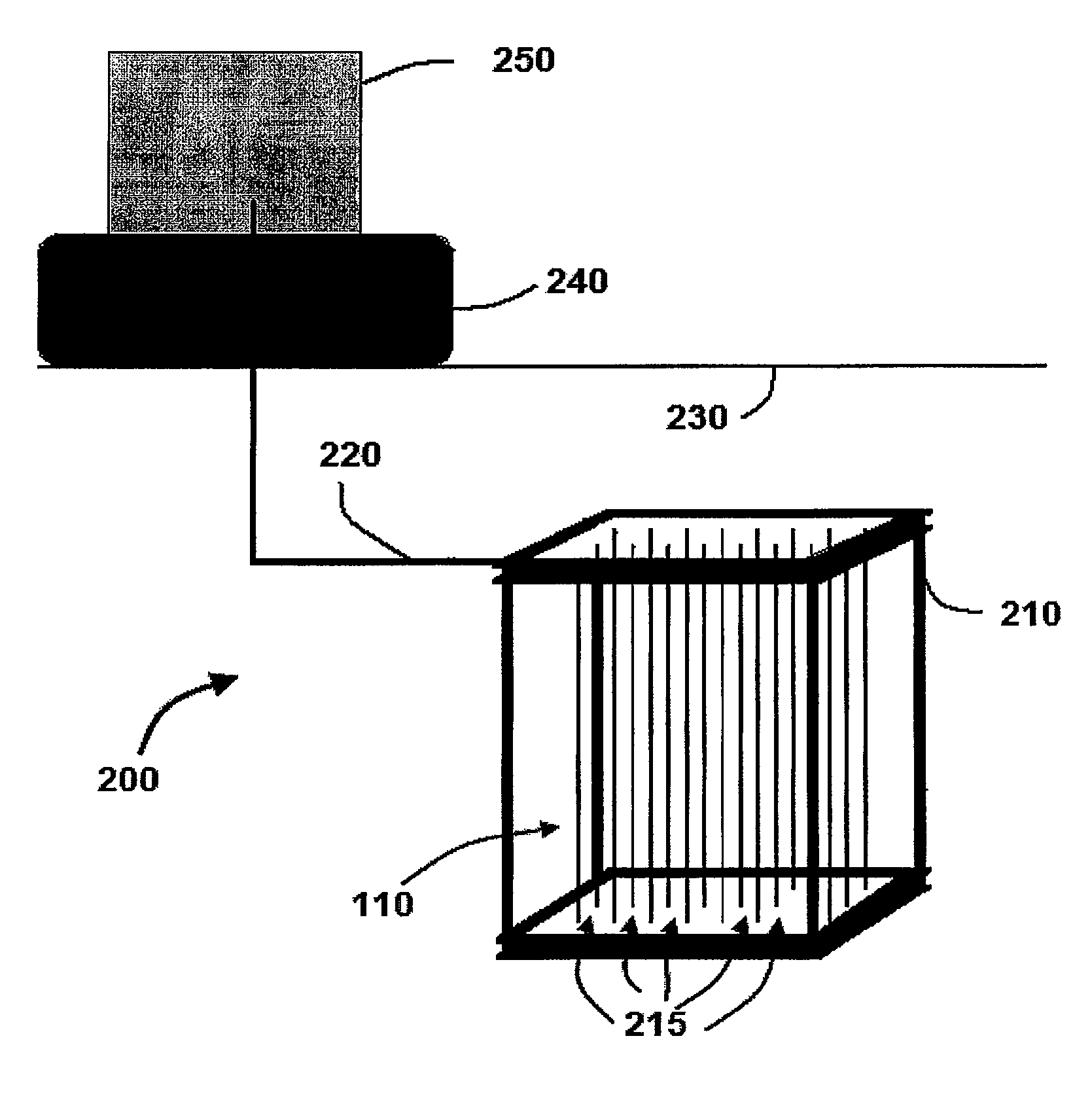
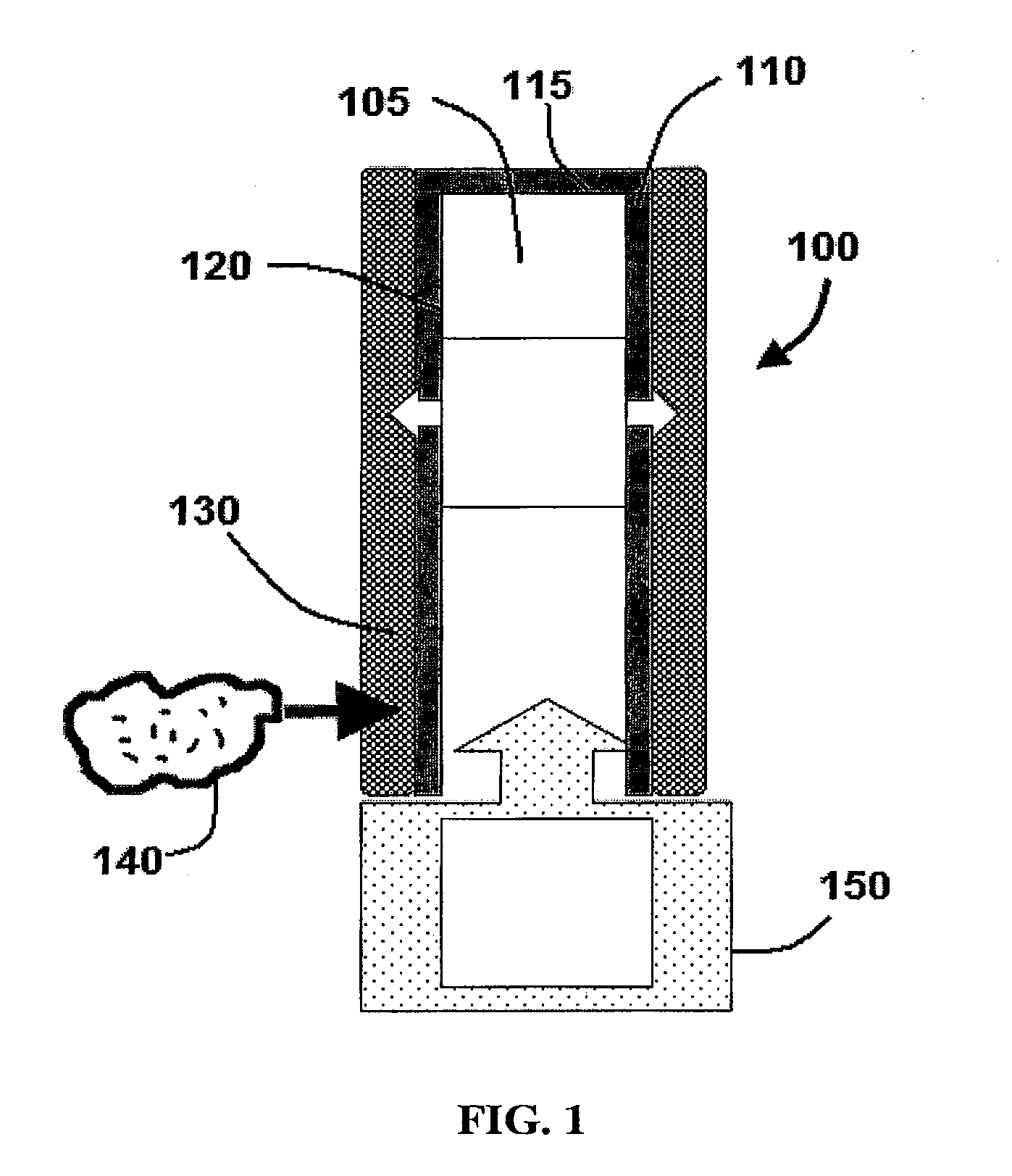
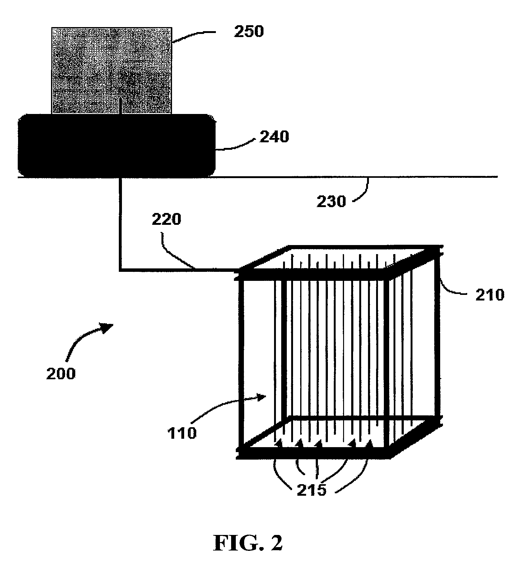
[0006]As illustrated in the exemplary embodiment of FIG. 1, an MBfR 100 is coupled to a source of reactive gas 150. Reactive gas 150 is delivered to a lumen 105 of tubular member or a hollow fiber 110 in the MBfR 100 and diffuses through the wall 120. In exemplary embodiments, hollow fiber 110 may comprise an end member 115 such as a cap, plug, or other sealing member to restrict gas 150 from exiting lumen 105 without diffusing through wall 120. It is understood that the term “hollow” as used herein is to be interpreted broadly and does not require that the fiber or member be completely void of material in the lumen or central portion. For example, a hollow fiber may comprise a porous material in the lumen that is capable of allowing the reactive gas to pass through the material and diffuse through the wall. It is also understood that the hollow fibers may be of various sizes. For example, in certain embodiments, hollow fibers 110 may have a diameter of approximately, 10 μm, 20 μm, ...


PUM

PropertyMeasurementUnit
diameteraaaaaaaaaa
diameteraaaaaaaaaa
diameteraaaaaaaaaa

Abstract

A method, apparatus, and system for removing contaminants from a body of surface water. The method and apparatus may include tubular members such as hollow-fiber components. The tubular members have a reactive gas diffused through wall of the member. Contaminants in the water can be removed when the reactive gas reacts with bacteria on the tubular member.

Description

CROSS-REFERENCE TO RELATED APPLICATIONS[0001]This application is U.S. national phase fliling under 35 U.S.C. §371 of PCT / US2009 / 035228 filed Feb. 26, 2009, which claims priority to U.S. Provisional Patent Application No. 61 / 033,623 filed on Mar. 4, 2008, the disclosure of which is herein incorporated by reference.BACKGROUND INFORMATION[0002]Surface waters throughout the world are contaminated with nutrients that come from a range of non-point sources (e.g., agricultural and storm water run-off, high-density animal operations, and atmospheric deposition), and inadequately treated wastewaters. Chief among the contaminants is nitrogen, which is present as nitrate (NO3−), nitrite (NO2−), and ammonium (NH4+). Excess concentrations of these nutrients cause eutrophication of natural water bodies, particularly the ocean, estuaries, lakes, and reservoirs. Up to the present time, no reliable means is available to remove these nitrogen-containing compounds from surface water once the water is ...

Claims


Application Information

Patent Timeline
Patent Type & Authority Patents(United States)
IPC IPC(8): C02F3/02
CPCC02F3/102C02F3/26C02F3/302C02F2101/106C02F2101/12C02F2101/16C02F2101/163C02F2101/166C02F2101/22C02F2101/30C02F2101/322C02F2101/345C02F2101/36C02F2101/38C02F2103/007Y02W10/10
Inventor RITTMANN, BRUCE E.
Owner RITTMANN BRUCE E
Why Eureka
Try Eureka