Optical access system, optical switching unit and optical line terminal

a technology of optical switching unit and optical access system, which is applied in the field of optical access system, can solve the problems of signal power, shortening the communicable distance, and not always ensuring the satisfaction of secrecy,

Inactive Publication Date: 2013-03-19
HITACHI LTD
View PDF10 Cites 7 Cited by
  • Summary
  • Abstract
  • Description
  • Claims
  • Application Information

AI Technical Summary

Benefits of technology

[0007]With technologies described in IEICE TRANS. COMMUN., VOL. E89-B, NO. 3 pp. 724-730 and IEICE TRANS. COMMUN., VOL. E89-B, NO. 11 pp. 3021-3031, a unit that makes a switch to an output port for a desired ONU splits an optical signal sent from the OLT into a signal for the optical switch and a signal for a circuit that performs frame reading processing. In the frame reading circuit, a logical link identifier (LLID) set in the preamble part of an EPON frame is used in switching output ports of the optical switch. A delay circuit needs to be provided downstream of the optical switch in order to delay signal transmission by the amount of time required for processing in the frame reading circuit. According to IEICE TRANS. COMMUN., VOL. E89-B, NO. 11 pp. 3021-3031, when the delay circuit is built from an optical fiber, the optical fiber measures 42.4 m in length and hinders the downsizing of the output port switching unit.
[0009]According to this invention, the optical line terminal (OLT) determines a switching control schedule of an optical switch and data frame transmission timing, and conveys the determined switching control schedule and transmission timing to the optical switching unit (OSW), thereby eliminating the need for delay control of an optical signal in the OSW. The OSW can thus be made small in size.

Problems solved by technology

The resultant problem is that satisfactory secrecy is not always guaranteed.
Further, signal branching in the splitter lowers the optical signal power and presents a problem that an increase in number of branches shortens the communicable distance.

Method used


Image

  • Optical access system, optical switching unit and optical line terminal
  • Optical access system, optical switching unit and optical line terminal
  • Optical access system, optical switching unit and optical line terminal

Examples


first embodiment

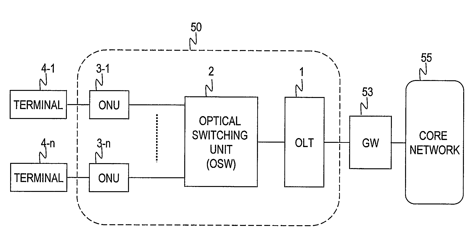
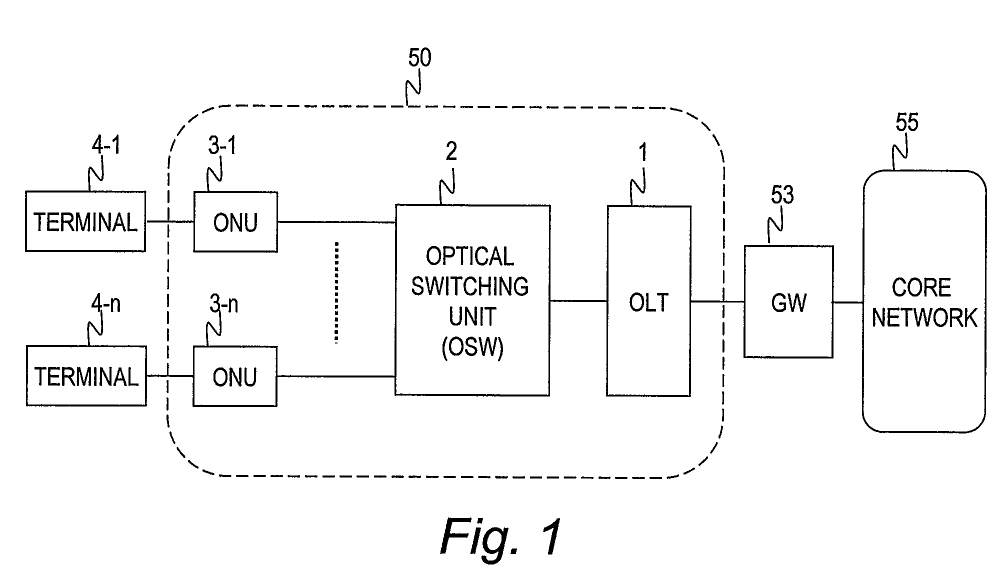
[0035]FIG. 1 is a block diagram illustrating a configuration example of a network according to this invention.

[0036]An optical access system 50 of the first embodiment includes an optical line terminal (OLT) 1, an optical switching unit (OSW) 2, and optical network units (ONUs) 3. The optical access system 50 includes as many ONUs 3 as the count of users. The ONUs 3 are referred to as ONUs 3 when there is no need to discriminate one from another, and referred to as ONUs 3-1 to 3-n when discriminating one from another is necessary.

[0037]A plurality of user terminals 4 (4-1 to 4-n) are connected to the ONUs 3. The user terminals 4 communicate with a core network 55 via the optical access system 50 and a gateway (GW) 53.

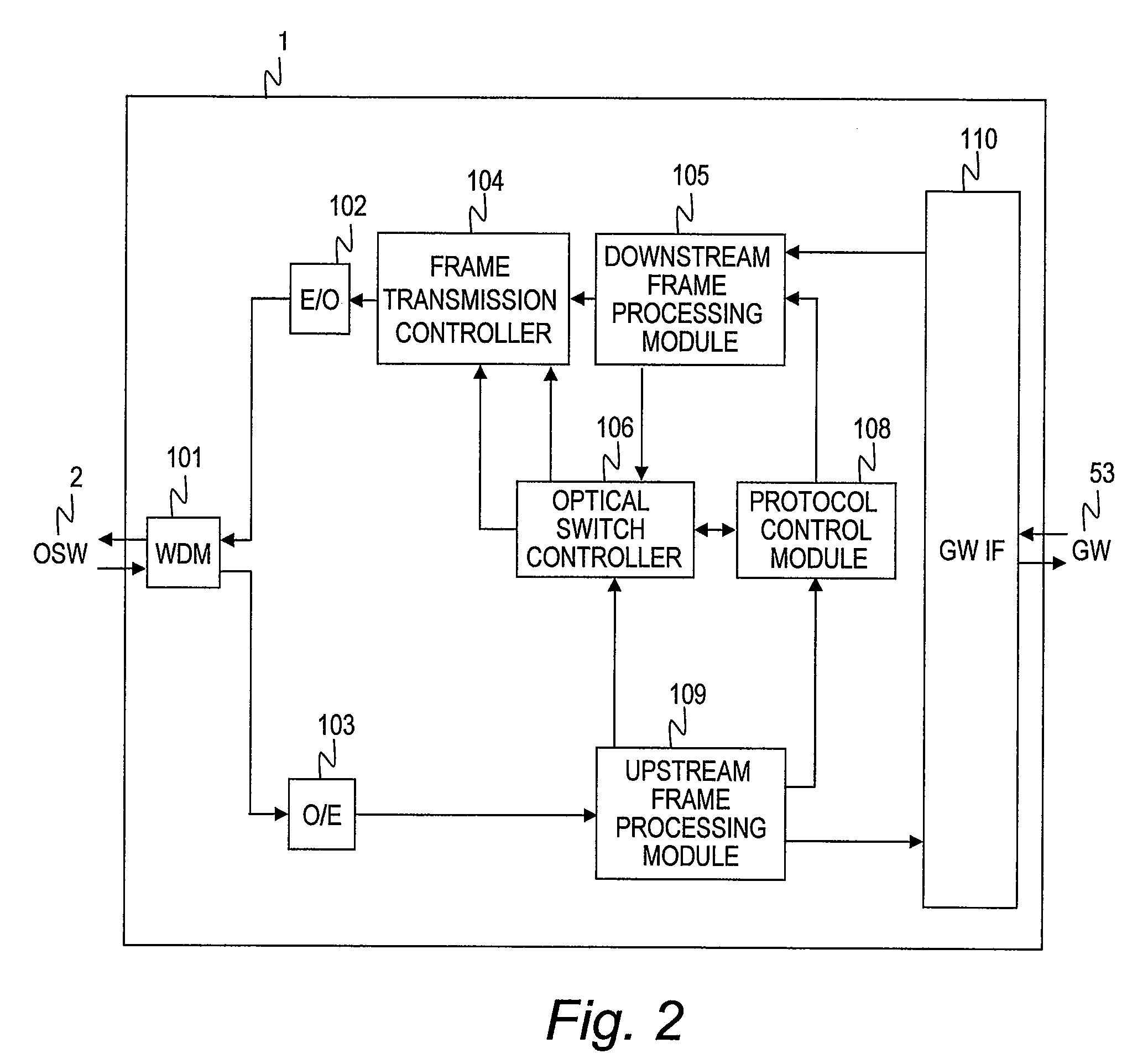
[0038]FIG. 2 is a block diagram illustrating a configuration example of the OLT 1 according to the first embodiment of this invention.

[0039]The OLT 1 includes a multiplexing / demultiplexing module (WDM) 101, an electrical-optical signal converter (E / O converter) 102, an ...


PUM


Abstract

Provided is an optical access system, including: an optical line terminal, a plurality of optical network units and an optical switching unit. The optical line terminal sends to the optical switching unit a control frame including a switching time when the optical switching unit is to make a switch from one of the optical communication paths between the optical line terminal and the plurality of optical network units to another, and an identifier of an optical communication path to which the switch is made in order to switch the optical communication paths between the optical line terminal and the plurality of optical network units. The optical switching unit switches the optical communication paths between the optical line terminal and the plurality of optical network units based on the switching time and the identifier of the optical communication path after switching which are included in the control frame.

Description

CLAIM OF PRIORITY[0001]The present application claims priority from Japanese patent application JP 2008-190494 filed on Jul. 24, 2008, the content of which is hereby incorporated by reference into this application.BACKGROUND OF THE INVENTION[0002]This invention relates to an optical access system, and more particularly, to a technology of controlling optical communication path switching in an optical access system that uses an optical switch to switch optical communication paths.[0003]An optical access system with a passive optical network (PON) has become popular as a way to access the Internet at high speed. Variations of PON technology include an Ethernet passive optical network (EPON) defined in IEEE Std 802. 3TM-2005 and a Gigabit-capable passive optical network (GPON) defined in ITU-T Recommendation G. 984.1.[0004]A PON includes an optical line terminal (OLT), which terminates an optical fiber on the side of a central office of a telecommunications carrier, an optical network ...

Claims


Application Information

Patent Timeline
Patent Type & Authority Patents(United States)
IPC IPC(8): H04J14/00H04B10/00H04B10/27H04B10/272H04L12/44
CPCH04Q11/0067H04Q2011/0045H04Q2011/0064
Inventor WAKAYAMA, KOJIIKEDA, HIROKIOKUNO, MICHITAKASAKAMOTO, KENICHI
Owner HITACHI LTD
Why Eureka
Try Eureka