Method of manufacturing hollow microneedle structures

a manufacturing method and technology of microneedles, applied in the field of manufacturing hollow microneedles, can solve the problems of not meeting the required needle length, unable to ensure the verticality and uniformity of the microneedle, and the needle cannot ensure the verticality and uniformity of the microneedle, and achieves the effect of process simplification

Inactive Publication Date: 2013-03-26
ELECTRONICS & TELECOMM RES INST
View PDF26 Cites 12 Cited by
  • Summary
  • Abstract
  • Description
  • Claims
  • Application Information

AI Technical Summary

Benefits of technology

[0016]The present invention is directed to a method of manufacturing a hollow microneedle structure, which can ensure such a hardness as to penetrate the skin and such a length as to reach a capillary vessel. Also, the method of manufacturing the hollow microneedle structure may provide a microneedle structure having vertical needles with a uniform inner diameter using a simple process.
[0022]The method may further include chemically treating the hollow of the microneedle structure to prevent hardening of a biomaterial.

Problems solved by technology

However, conventional needles used to collect biomaterials, such as blood, are practically problematic because they may cause pain during use and inflict external injuries.
However, this technique requires an additional etching process to provide a hollow needle shape, or does not satisfy a required needle length.
Meanwhile, although a microneedle having a sufficient length has recently been proposed using a drawing method, the proposed microneedle neither ensures verticality and uniformity nor realizes process simplification.

Method used


Image

  • Method of manufacturing hollow microneedle structures
  • Method of manufacturing hollow microneedle structures
  • Method of manufacturing hollow microneedle structures

Examples


Embodiment Construction

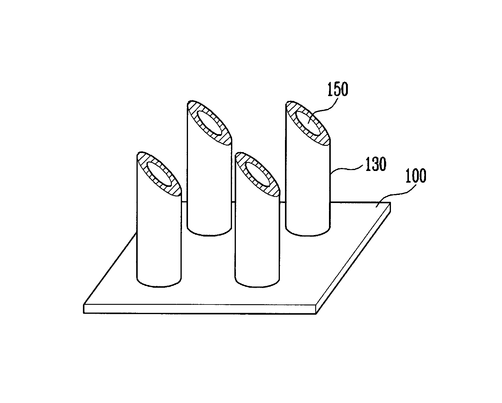
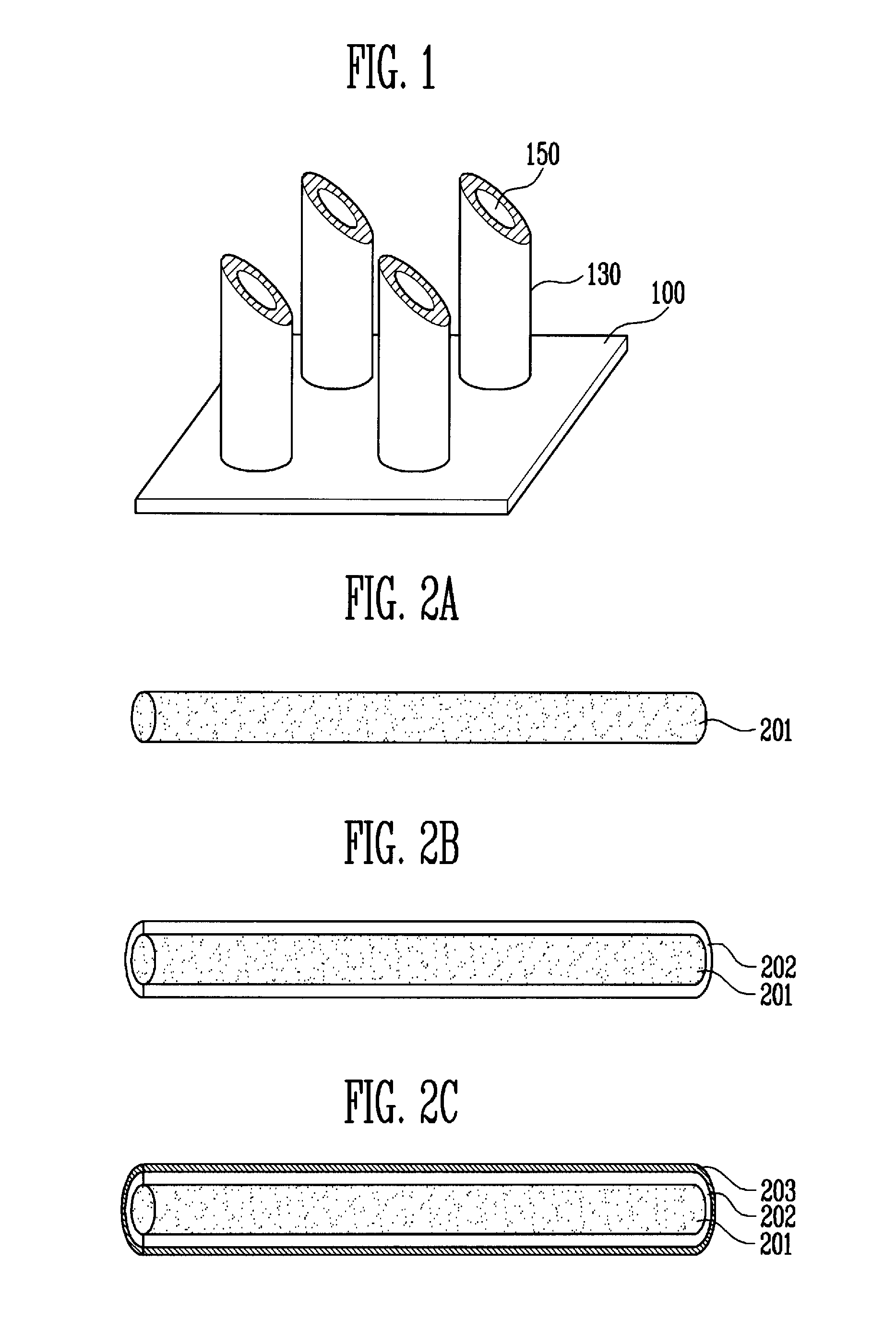
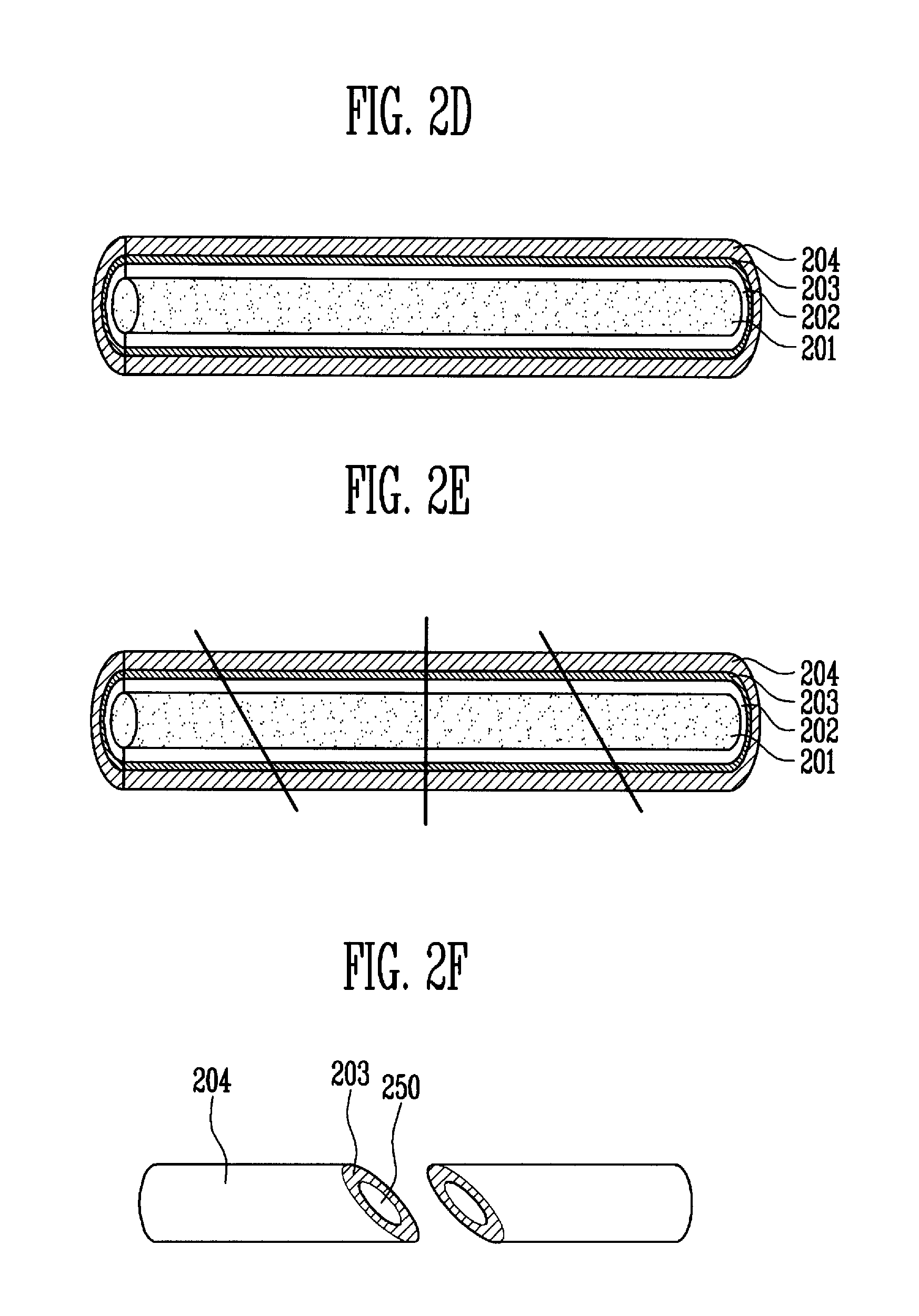
[0033]The present invention will be described more fully hereinafter with reference to the accompanying drawings, in which exemplary embodiments of the invention are shown. This invention may, however, be embodied in many different forms and should not be construed as being limited to the embodiments set forth herein. Rather, these embodiments are provided so that this disclosure is thorough and complete and fully conveys the concept of the invention to those skilled in the art. In the drawings, portions irrelevant to a description of the invention are omitted for brevity, and like numbers refer to like elements throughout.

[0034]As used herein, the terms “comprises” and / or “comprising,” when used in this specification, specify the presence of stated features, integers, steps, operations, elements, and / or components, but do not preclude the presence or addition of one or more other features, integers, steps, operations, elements, components, and / or groups thereof.

[0035]Hereinafter, a...


PUM

PropertyMeasurementUnit
inner diameteraaaaaaaaaa
lengthaaaaaaaaaa

Abstract

Provided is a method of manufacturing a hollow microneedle structure. The method includes coating a hollow core having a predetermined section and being long in a lengthwise direction with a coating solution, and solidifying the coating solution to form a coating layer, depositing a metal seed layer on the coating layer, plating the seed metal layer with a metal to form a plated layer, cutting the hollow core having the plated layer at an inclination angle with respect to the lengthwise direction for form a surface inclination, and removing the hollow core and the coating layer to form a hollow microneedle structure. Thus, the hollow microneedle structure can be manufactured to have such diameter, length, hardness, and inclination angle as to minimize pain. By use of the hollow core, the microneedle structure can have vertical microneedles with a uniform inner diameter.

Description

CROSS-REFERENCE TO RELATED APPLICATION[0001]This application claims priority to and the benefit of Korean Patent Application No. 10-2009-0061620, filed Jul. 7, 2009, the disclosure of which is incorporated herein by reference in its entirety.BACKGROUND[0002]1. Field of the Invention[0003]The present invention relates to a method of manufacturing hollow microneedles, and more specifically, to a method of manufacturing hollow microneedles in which a hollow is formed using microthreads.[0004]2. Discussion of Related Art[0005]In the field of bio-microelectromechanical systems (bio-MEMS) technology, samples may need to be pretreated in order to enable early detection and chemical analysis for diseases on small chips. This requires collecting blood while minimizing pain. Accordingly, an essential component called a microneedle is required.[0006]In general, needles are variously utilized in hospitals. For example, the needles are used to collect biomaterials, such as blood, in order to det...

Claims


Application Information

Patent Timeline
Patent Type & Authority Patents(United States)
IPC IPC(8): B23P25/00B05D3/12B22D11/126A61M5/32
CPCA61B5/685A61M37/0015A61B5/14514A61M2037/0053Y10T29/4998Y10T156/1062Y10T29/49885B21G1/08A61M5/178A61M37/00
Inventor LEE, DAE SIKYOON, YONG SUNJUNG, MOON YOUNPARK, SEON HEE
Owner ELECTRONICS & TELECOMM RES INST
Why Eureka
Try Eureka